BLDC motor current sensing helps a drive control torque, limit overloads, and understand what the motor is doing under load. The useful question is not simply whether a controller measures current. It is where the measurement happens, when it is sampled, and how the drive uses it.
What the current measurement tells you
A drive converts DC supply power into switched currents in the motor windings. Those currents produce torque and winding heat. A current signal can feed a regulation loop, trigger a protective response, or supply diagnostic information. These functions have different requirements: a slow display value is not a substitute for fast fault detection.
Current is also only part of the picture. Speed, rotor position, bus voltage, temperature, and the mechanical load help explain whether a reading is reasonable. Our brushless motor vector control guide explains how current feedback fits into FOC.
Phase current and supply current are different
Phase current flows through a motor winding. Supply current flows between the power source and the drive. PWM switching, recirculation paths, and the DC-link capacitor mean their instantaneous values are not interchangeable. A handheld meter at the supply input cannot show every winding-current peak.
Read the motor and controller specifications carefully. “10 A” might describe a continuous phase rating, a short-duration peak, or a supply limit. Also check whether the value is RMS or peak and what cooling conditions apply. Comparing numbers without their definitions can lead to an undersized drive or an unnecessarily large one.
BLDC motor current sensing methods compared
On a phone, swipe horizontally to read the table.
| Method | Useful feature | What to check |
|---|---|---|
| DC-link shunt | Low component count; can support phase reconstruction | Sampling windows, PWM strategy, and reconstruction limits |
| Low-side phase shunts | Measurements near the power-stage ground | Valid switching intervals, ground layout, and amplifier settling |
| In-line phase sensing | Measures current in the motor phase path | Switching common-mode transients, input range, and recovery |
| Magnetic current sensor | Can provide galvanic isolation, depending on the device | Bandwidth, offset, temperature drift, and certified isolation ratings |
| Integrated sensing | May reduce external parts | Accuracy, calibration, temperature behavior, and protection coverage |
How a shunt measurement works
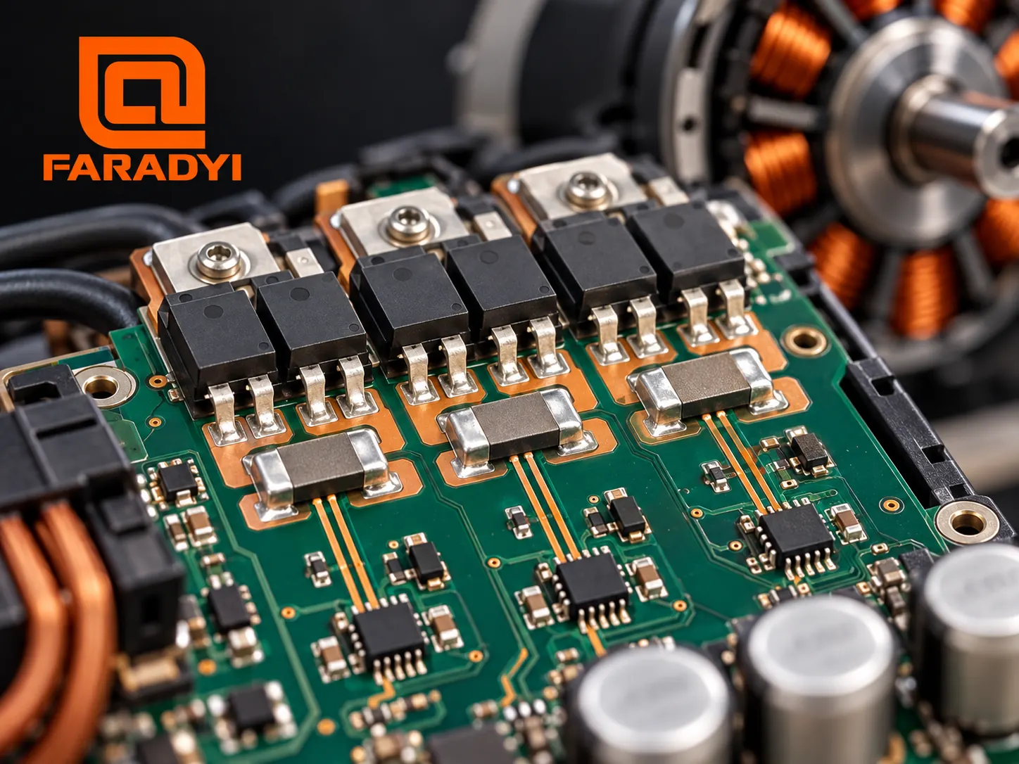
A shunt creates a small voltage proportional to current: V = I × R. An amplifier and ADC turn that voltage into a usable measurement. As an illustrative calculation, 10 A through 5 mΩ produces 50 mV and dissipates 0.5 W. That is not a component recommendation: pulse loading, temperature rise, tolerance, and PCB heat flow still need review.
Use the component manufacturer’s recommended Kelvin connections so the sense inputs measure the shunt rather than an unintended length of power copper. Keep the measurement path away from switching loops and follow the amplifier’s layout and filtering guidance.
Why one sensor can require more software
A DC-link shunt does not directly report all three phase currents at every instant. Reconstruction relates sampled bus current to known inverter states. Short active intervals can leave too little time for switching transients to settle and the ADC to acquire a valid value. The drive may need PWM adjustments or other measures to maintain usable windows.
Two measured phase currents can also be used to calculate the third in a suitable three-wire system. The measurements must still be valid and appropriately timed. Sensor count alone does not establish control quality.
Sampling, filtering, and isolation
Place ADC sampling inside the valid measurement interval. Account for switching noise, amplifier recovery, conversion time, and the controller’s update timing. Adding a large filter may make a trace look cleaner while delaying the information needed by the control loop.
Isolation is a system-design decision, not a universal rule triggered above 12 V. Review the working voltage, accessible interfaces, grounding, transients, and applicable equipment requirements. A Hall-effect device is not automatically a suitably rated isolation barrier; check the actual datasheet and construction.
When the reading looks wrong
- Check the definition. Confirm phase versus supply current, RMS versus peak, and the measurement location.
- Check zero and scaling. Review offset calibration, shunt value, gain, ADC reference, polarity, and software units.
- Compare timing. Look for errors tied to commutation edges, duty cycle, or an invalid sample window.
- Separate noise from load. Compare repeatable electrical disturbances with changes caused by acceleration, friction, or a stalled mechanism.
- Validate through the cycle. Check startup, loaded running, braking, and temperature rise with suitable test equipment and qualified personnel.
If current rises with temperature or sustained load, review the motor overheating guide. Increasing a current limit before finding the cause can simply move the problem elsewhere.
Choose the motor and driver together
A small fan, a reversing feeder, and a robot joint place different demands on the drive. Specify the required torque and speed cycle, then choose the sensing and control arrangement that supports it. Current limiting does not replace a complete motor, inverter, and machine protection review.
Browse Faradyi brushless motors and ask which compatible drive configuration supports your application. Send the supply range, continuous and peak torque, loaded speed, duty cycle, motor electrical data, feedback interface, cooling conditions, and expected quantity. Include the definitions of any current limits already specified.
Contact Faradyi for a motor-and-driver selection review rather than selecting a combination from current labels alone.
Frequently asked questions
Does a sensorless BLDC motor still need current sensing?
It may. “Sensorless” usually refers to rotor-position sensing. The controller can still measure current for regulation, estimation, or protection.
Can supply current be used as motor phase current?
Not as a direct replacement. Some drives reconstruct phase currents from synchronized DC-link samples, but that is different from reading average supply current.
Is a shunt always better than a Hall-effect current sensor?
No. Compare the required range, error budget, bandwidth, losses, isolation, board space, and total implementation cost.
Make the current signal useful
Good BLDC motor current sensing connects the sensor location, analog circuit, PWM timing, and control software. Confirm that the resulting measurement answers the intended control or protection question, then test the complete drive under its real load cycle.
Technical references