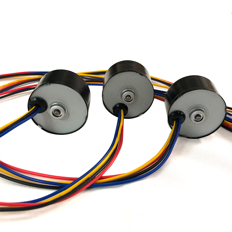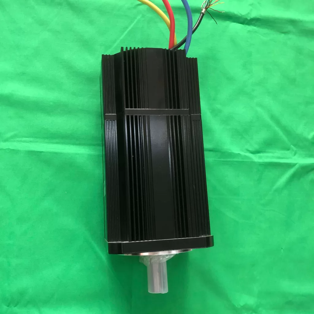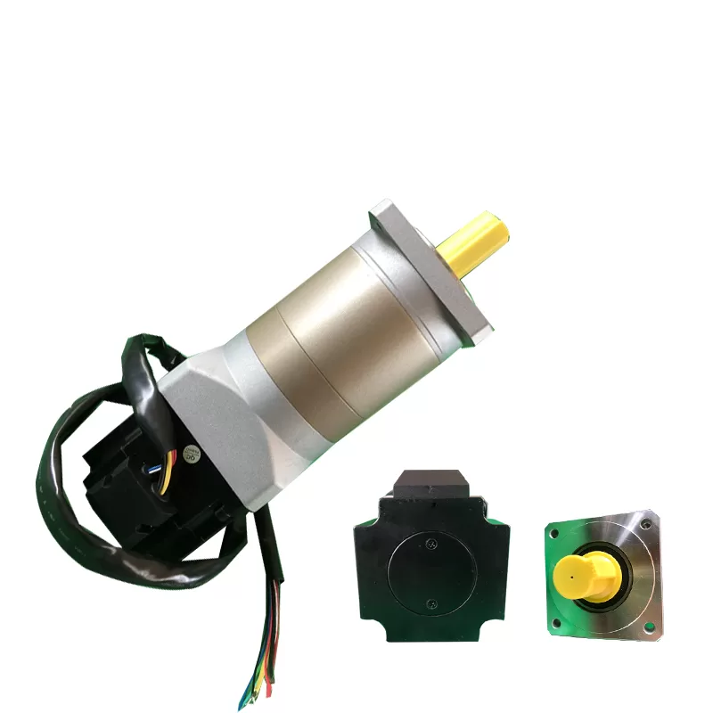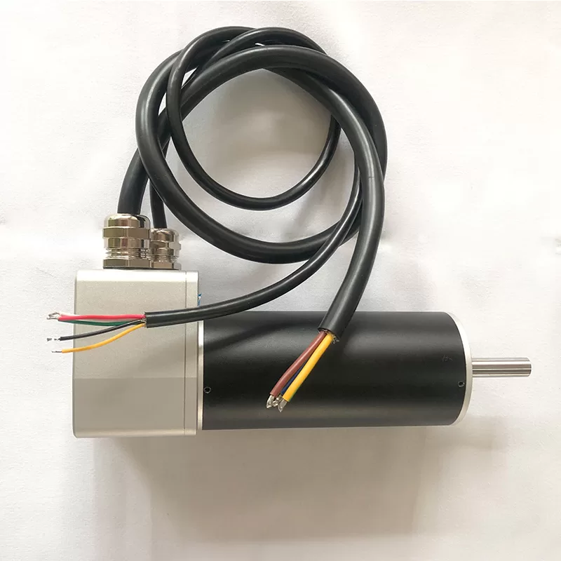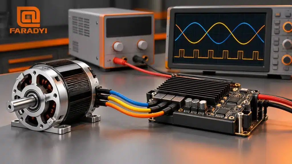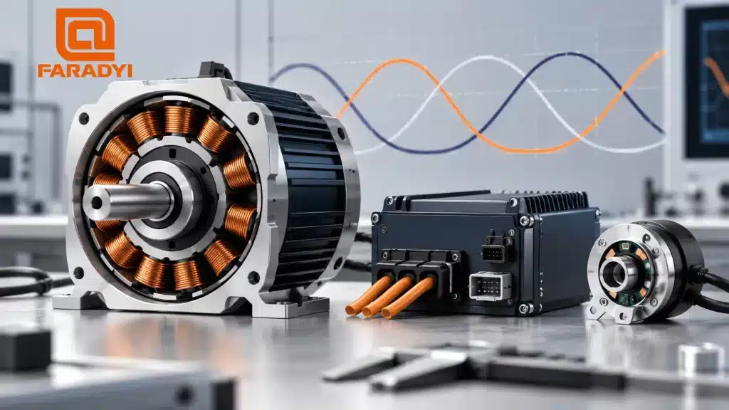
Brushless motor vector control, usually called field-oriented control (FOC), regulates motor current relative to the rotor’s magnetic field. Instead of trying to control three changing phase currents independently, the controller represents them as two components in a rotating reference frame. This makes torque control easier to manage as speed and load change.
Quick answer: FOC uses current measurements and rotor-angle information to control the d-axis and q-axis current components. It can deliver smooth torque and responsive speed control, but its results depend on motor characteristics, feedback quality, current sensing, tuning, and voltage and current limits.
How brushless motor vector control works
A brushless motor’s stator has phase windings, while the rotor carries permanent magnets. To produce useful torque, the controller must coordinate winding current with rotor position. Six-step commutation switches between discrete states. FOC continuously calculates the current vector relative to the rotor.
The physical phase currents still change with time. What becomes approximately steady during constant operation is their representation in the rotating d-q frame. That distinction matters: coordinate transformations simplify the control problem, but they do not remove electrical dynamics or processing delays.
1. Measure current and determine electrical angle
The drive samples current and obtains rotor electrical angle from an encoder, resolver, suitable Hall-based method, or sensorless estimator. Electrical angle includes the effect of the motor’s pole-pair count; it is not always the same as mechanical shaft angle.
2. Transform phase currents into d-q components
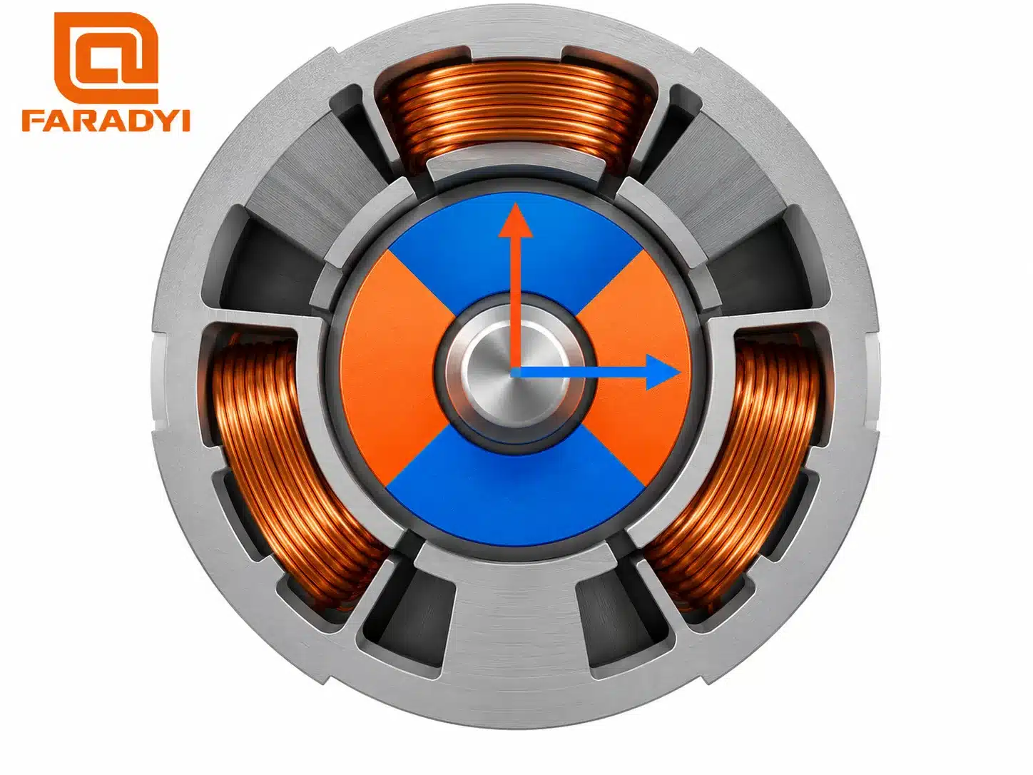
The Clarke transform maps three-phase currents into a stationary two-axis representation. The Park transform then rotates that representation using the electrical angle. The d-axis aligns with the rotor magnetic field; the q-axis is perpendicular to it.
3. Regulate the current components
Current controllers compare measured d- and q-axis currents with their references and calculate voltage commands. A common surface-magnet motor strategy uses approximately zero d-axis current below the field-weakening region, while q-axis current primarily controls torque.
Zero d-axis current is not a universal rule. Interior-magnet machines may use a different current allocation for maximum torque per ampere, and field weakening can require negative d-axis current. The strategy must respect motor and drive limits.
4. Apply the voltage commands through the inverter
Inverse transformations return the commanded voltage vector to the stationary frame. PWM, often space-vector modulation, controls the inverter switches to produce the required phase voltages. An outer speed loop can request q-axis current; a position loop may sit outside that when positioning is needed.
FOC, sinusoidal commutation, and six-step control
FOC often produces near-sinusoidal phase currents. Calling it the opposite of sinusoidal control is misleading. “Sinusoidal commutation” describes the waveform or commutation approach; FOC also specifies how current is controlled relative to rotor angle. Implementations can overlap.
| Approach | Typical control method | Selection tradeoff |
|---|---|---|
| Six-step commutation | Switches phase energization through discrete electrical sectors | Often simpler; torque ripple and acoustic behavior depend on motor and implementation |
| Basic sinusoidal commutation | Applies smooth phase commands using rotor-angle information | Can improve smoothness; waveform alone does not specify current-loop performance |
| Field-oriented control | Regulates d-q current components in the rotor reference frame | Offers flexible torque control; requires accurate sensing, angle information, and commissioning |
On a phone, swipe the table horizontally.
When vector control is useful
FOC is worth evaluating when the application needs controlled torque, smooth low-speed motion, frequent changes in load, or a wide useful speed range. Examples include servo axes, robot joints, pumps, and quiet ventilation equipment. The requirements differ: a positioning axis may need an encoder, while a continuously running fan may suit a sensorless implementation.
For a simple load that already meets its noise, efficiency, and response targets, a more complex controller may offer little practical benefit. Compare complete motor-drive combinations at the same operating points rather than assuming that the FOC label guarantees better efficiency.
What FOC does not solve automatically
- Low-speed position estimation: conventional back-EMF observers lose useful information near standstill. Some advanced methods address this, but their capability is motor- and controller-specific.
- High-speed limits: bus voltage, back-EMF, electrical frequency, sampling, and available control bandwidth still restrict performance.
- Torque ripple: cogging, back-EMF harmonics, angle error, and current distortion can remain even with FOC.
- Thermal capacity: a well-controlled current can still overheat a motor if its magnitude or duration exceeds the rated duty.
Field weakening can extend the speed range of a suitable system, but it does not create unlimited power or remove rotor-speed and magnet limits. Use only a validated field-weakening strategy for the actual motor.
Choosing a motor and FOC controller together
- Define continuous and peak torque, speed range, duty cycle, and required response.
- Match supply voltage, phase-current capability, winding resistance and inductance, pole pairs, and feedback interface.
- Confirm the required starting torque and low-speed behavior. For startup details, read our BLDC startup and speed-control guide.
- Follow the drive manufacturer’s motor-identification and feedback-alignment procedure.
- Validate current, speed response, temperature, noise, and fault handling under the real load before approving the combination.
Begin with Faradyi’s brushless DC motor range. If mechanical reduction is required, review gear ratio and motor-controller selection as part of the same decision.
Frequently asked questions
Is vector control the same as FOC?
In this brushless permanent-magnet motor context, vector control usually refers to field-oriented control. Check the drive’s actual operating modes because marketing terms do not always describe the same implementation.
Does FOC require an encoder?
No. Rotor angle can come from several feedback or estimation methods. An encoder may be appropriate for precise positioning or demanding low-speed operation; a compatible sensorless estimator may suit other loads.
Can any BLDC motor use an FOC controller?
Compatibility must be checked. The motor’s electrical parameters, back-EMF shape, feedback, speed, and thermal limits must fit the controller. A motor designed around strongly trapezoidal back-EMF may not give the same torque-ripple result as a sinusoidal machine.
Specify the performance your application needs
Brushless motor vector control is most useful when it solves a measurable motion or acoustic problem. To discuss a suitable motor, send Faradyi your voltage, continuous and peak torque, loaded speed, duty cycle, feedback needs, dimensions, environment, existing controller, and expected quantity. The goal is a verified motor-drive match, not simply a more advanced control label.
Technical references: Texas Instruments: FOC Made Easy for BLDC Motors; Microchip: Field-Oriented Control Algorithms.