Il existe une différence fondamentale entre le contrôle vectoriel et le contrôle par onde sinusoïdale des moteurs sans balais, à savoir la manière dont ils contrôlent le courant des moteurs sans balais. À mesure que la vitesse du moteur sans balais augmente, la bande passante du contrôleur PI pour le contrôle de l'onde sinusoïdale atteindra la limite, entraînant une défaillance du contrôle. En revanche, le contrôle vectoriel permet un contrôle précis du courant de la bobine du stator en contrôlant directement les composantes du courant vectoriel dans les directions parallèles et perpendiculaires du champ magnétique du rotor. Sous contrôle vectoriel, le contrôle de courant ne change plus avec le temps, mais devient un contrôle DC statique, éliminant ainsi les limitations de réponse en fréquence et de dérive de phase. Par conséquent, la qualité du courant en mode contrôle vectoriel n’a rien à voir avec la vitesse du moteur.
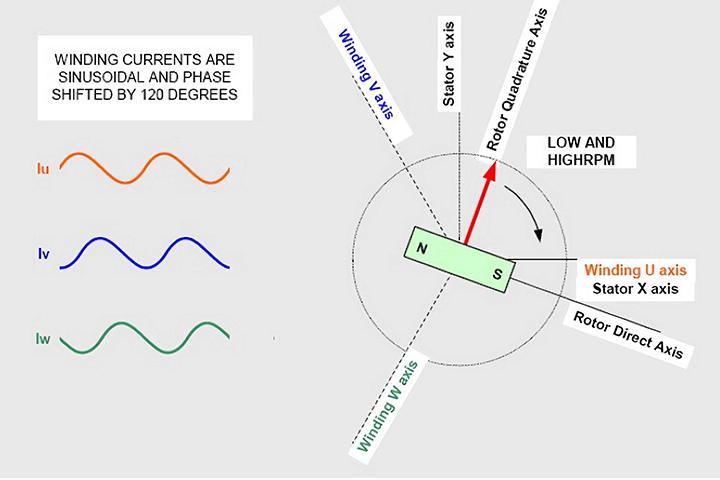
Dans le cas du contrôle vectoriel, nous contrôlons principalement les composantes du courant et de la tension du moteur sans balais dans les directions parallèles et verticales du champ magnétique du rotor. Cela signifie que nous devons calculer mathématiquement le courant mesuré par le moteur sans balais pour le convertir de la structure statique triphasée du stator en la structure dynamique dq du rotor (parallèle et perpendiculaire à la direction du champ magnétique du rotor). De même, la tension de commande à l'extrémité du moteur sans balais doit également être calculée mathématiquement pour la convertir de la structure dq du rotor en structure statique triphasée du stator, puis entrée dans la partie PWM pour modulation. Ces conversions nécessitent des capacités de traitement mathématique à grande vitesse, de sorte que le DSP et les processeurs hautes performances deviennent le cœur du contrôle vectoriel.
Bien que cette conversion puisse être effectuée en un seul calcul, pour des raisons de commodité de description, nous la divisons en deux étapes. Tout d'abord, le courant du moteur passe de la structure physique triphasée du stator avec une différence de phase de 120 degrés à une structure dq orthogonale dynamique à angle droit stable, puis convertit cette structure dynamique du stator en structure statique triphasée. du rotor. Pour garantir des résultats valides, ces calculs doivent être effectués dans une période d'échantillonnage du contrôleur PI. La conversion ci-dessus est à l'opposé de l'opération de conversion du signal de tension requis par le contrôleur PI de la structure dq à la structure triphasée de la bobine de stator.
Une fois le courant du moteur sans balais converti en une structure dq, le contrôle devient très simple. Nous avons besoin de deux contrôleurs PI : un pour contrôler le courant parallèle au champ magnétique du rotor et un pour contrôler le courant perpendiculaire au champ magnétique du rotor. Puisque le signal de commande du courant parallèle est nul, la composante de courant parallèle du moteur sans balais devient également nulle, convertissant tous les vecteurs de courant du moteur sans balais en courant vertical. Cela maximise l'efficacité des moteurs sans balais car seul le courant vertical peut produire un couple efficace. Un autre contrôleur PI est principalement utilisé pour contrôler le courant vertical afin d'obtenir le couple requis cohérent avec le signal d'entrée. Cela garantit que le courant vertical est contrôlé selon les besoins pour obtenir le couple requis.
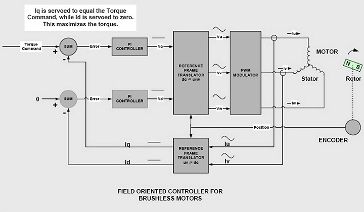
Les signaux de sortie des deux contrôleurs PI représentent le vecteur tension du rotor. Ces vecteurs de tension statique subissent une série de conversions de coordonnées de référence pour obtenir les signaux de commande de tension requis pour le pont de sortie. Ils sont d'abord convertis de la structure de référence dynamique dq du rotor en structure statique xy du stator. Le signal de tension est ensuite converti en structures physiques espacées de 120 degrés les unes des autres, et enfin entré dans les bobines triphasées U, V et W du moteur sans balais. Ces trois signaux de tension doivent être modulés PWM avant d'être entrés dans la bobine du moteur sans balais.
Le travail de conversion des signaux sinusoïdaux de courant et de tension variant dans le temps dans la bobine du moteur sans balais en un signal CC à structure dq est la conversion des coordonnées de référence.
La différence essentielle entre la commutation sinusoïdale et le contrôle vectoriel réside dans la manière dont la conversion des coordonnées et le contrôle du courant sont gérés. Dans la méthode de commutation d'onde sinusoïdale, nous effectuons d'abord la commutation, puis obtenons le courant d'onde sinusoïdale requis via le contrôle PI. Par conséquent, le contrôle PI du système traite principalement les signaux sinusoïdaux variables dans le temps du courant et de la tension du moteur sans balais, et les performances du moteur sans balais seront limitées par la bande passante du contrôleur et la dérive de phase. En contrôle vectoriel, le signal de courant est d'abord contrôlé par PI, puis subit un traitement de commutation à grande vitesse. Par conséquent, le contrôleur PI n'a pas besoin de traiter des signaux de courant et de tension variant dans le temps, et le système ne sera pas affecté par la bande passante et la dérive de phase du contrôleur PI.
Par conséquent, pourquoi le contrôle vectoriel est-il supérieur ?
La commande vectorielle permet au moteur de se comporter aussi bien à basse vitesse qu'à haute vitesse. En revanche, la commutation sinusoïdale permet un fonctionnement fluide à basse vitesse mais entraîne une réduction significative du rendement à haute vitesse. La commutation d'onde trapézoïdale se comporte normalement lorsque le moteur tourne à grande vitesse, mais elle provoquera des fluctuations de couple à basse vitesse. Par conséquent, la lutte anti- vectorielle est considérée comme la meilleure méthode de lutte contre moteurs sans balais.