Gear Reducers: What They Are and Why Machines Use Them
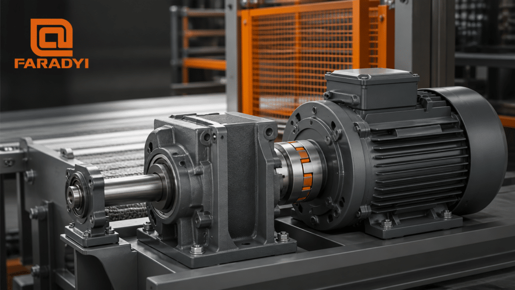
Gear reducers are enclosed mechanical transmissions that lower rotational speed while increasing available output torque. Positioned between a motor and the driven load, a reducer uses meshing gears to produce the ratio, shaft direction, mounting arrangement, and mechanical advantage a machine requires.
Reducers are found in conveyors, packaging machines, mixers, robotics, lifts, pumps, material-handling systems, machine tools, and automated equipment. Reliable selection requires more than choosing a ratio. Engineers must also evaluate torque, service factor, starting and shock loads, thermal capacity, backlash, shaft loads, duty cycle, lubrication, mounting, and environment.
How Does a Gear Reducer Work?
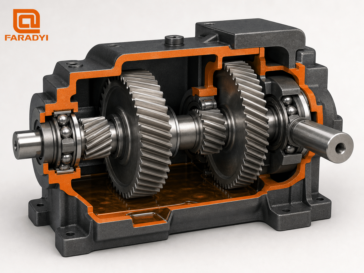
A simple reducer pairs a small input gear with a larger output gear. The larger gear rotates more slowly but delivers greater torque. Multiple gear stages can provide a higher total ratio in a compact housing. Bearings support the shafts, seals retain lubricant and exclude contaminants, and the housing maintains gear alignment while carrying reaction loads.
For an ideal reducer, the basic relationships are:
- Reduction ratio ≈ input speed ÷ output speed
- Output speed ≈ input speed ÷ ratio
- Output torque ≈ input torque × ratio × efficiency
These equations are estimates, not a substitute for catalog ratings. Efficiency changes with reducer type, ratio, speed, load, lubricant, temperature, and run-in condition. The selected unit must meet both mechanical and thermal limits.
Common Types of Gear Reducers
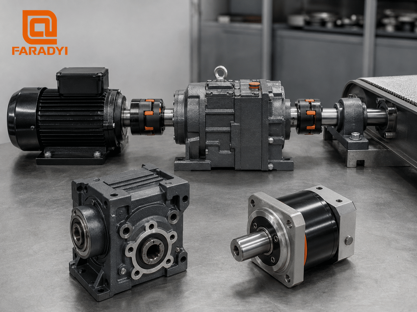
Helical gear reducers
Helical teeth engage gradually, supporting smooth power transmission and relatively quiet operation. Inline, parallel-shaft, and right-angle helical arrangements are widely used for conveyors, process equipment, and continuous-duty machinery. Helical gearing creates axial thrust, so bearing selection and housing stiffness matter.
Worm gear reducers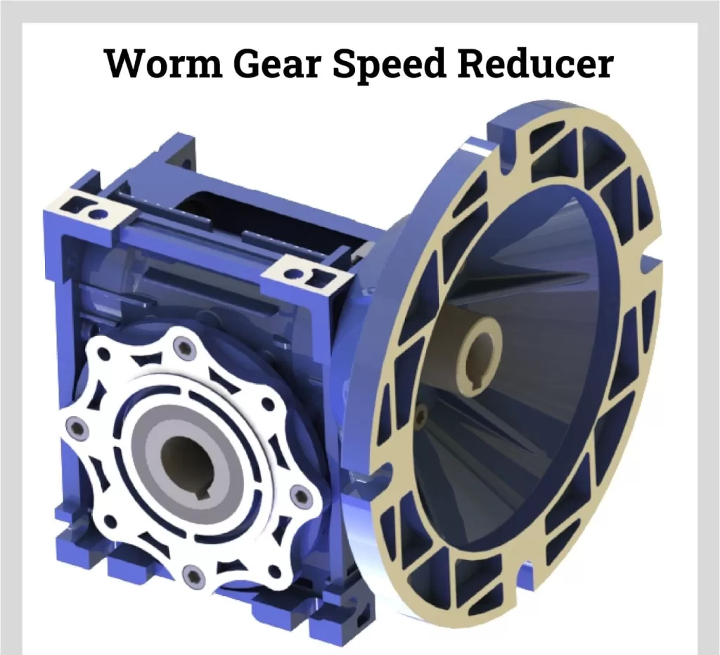
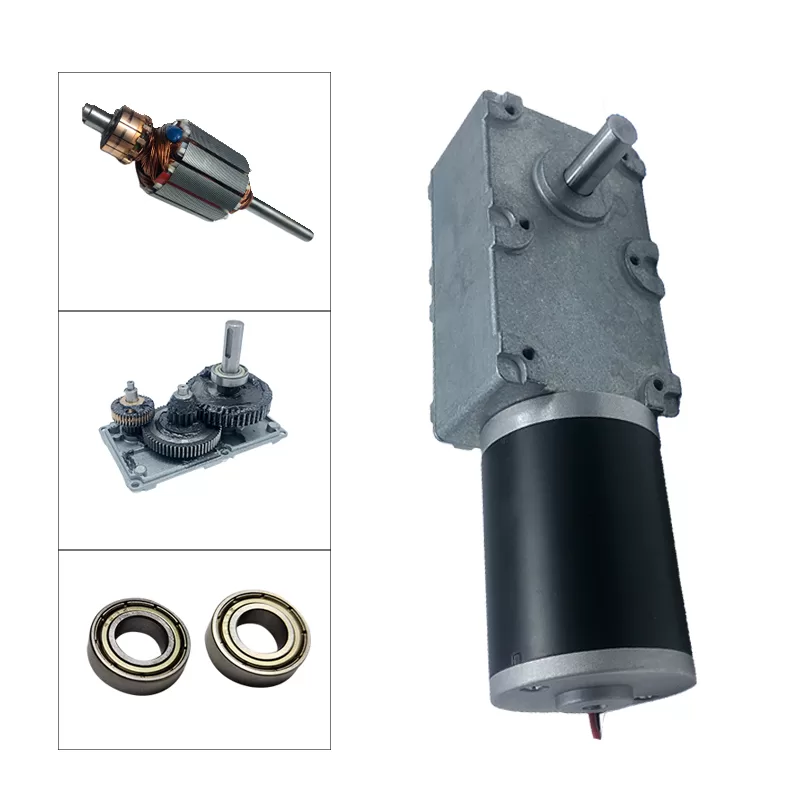
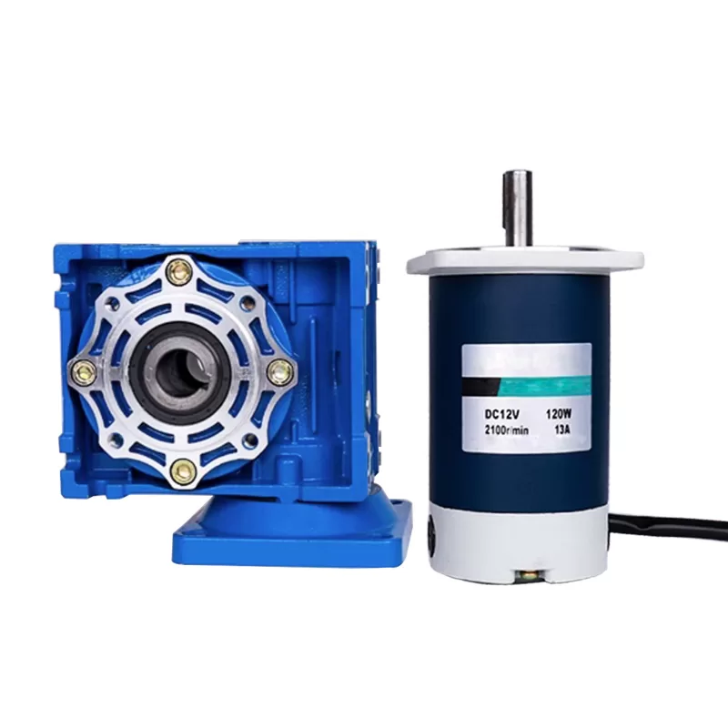
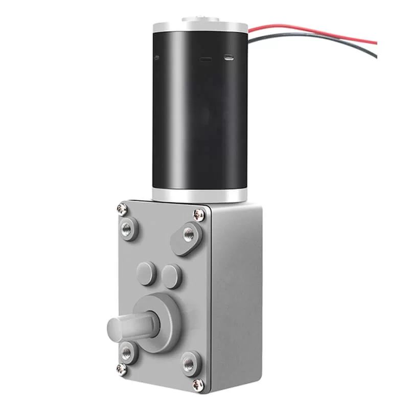
A worm shaft drives a worm wheel, normally producing a right-angle output and a substantial ratio in one stage. Worm units can be compact and quiet, but sliding tooth contact can generate more heat and reduce efficiency. Back-driving varies with lead angle, friction, load, wear, vibration, and lubrication. Never use presumed self-locking as a personnel-safety brake.
Planetary gear reducers
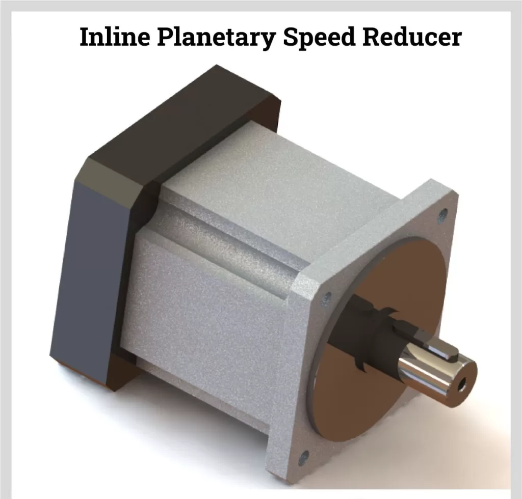
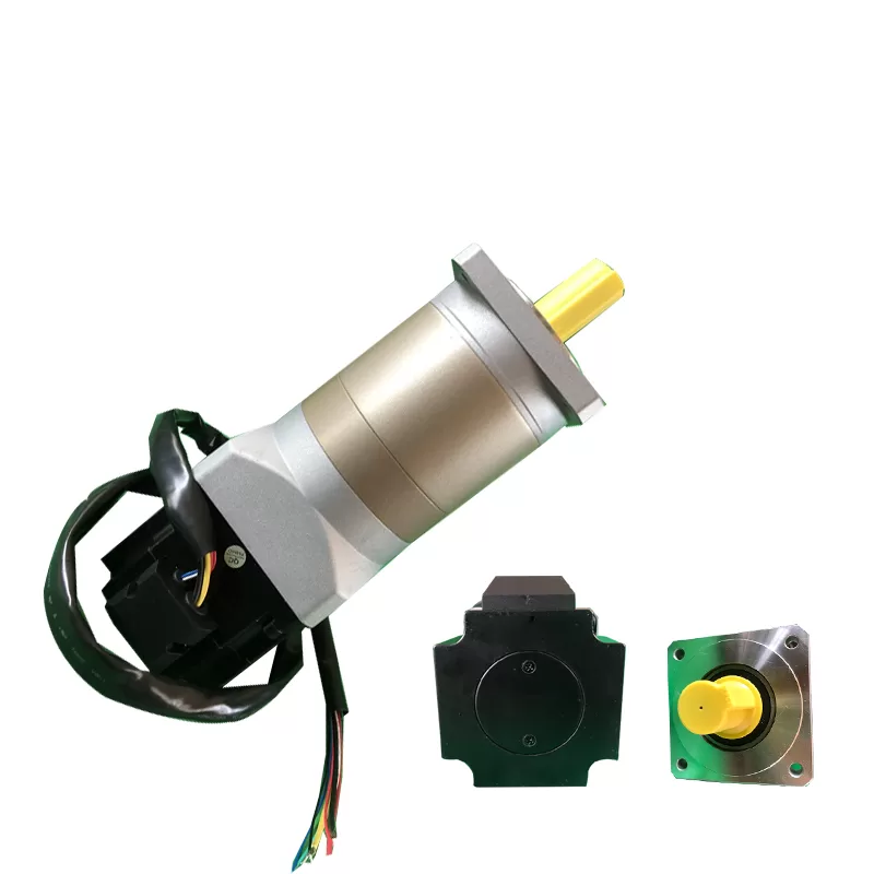
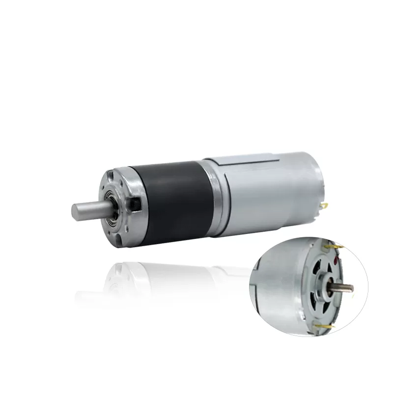
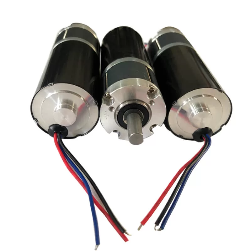
A planetary stage uses a sun gear, planet gears, carrier, and ring gear. Multiple load paths can provide high torque density, compact coaxial packaging, and favorable torsional stiffness. Precision grades are used in servo axes and robotics, while industrial planetary drives serve high-torque equipment.
Bevel and bevel-helical reducers
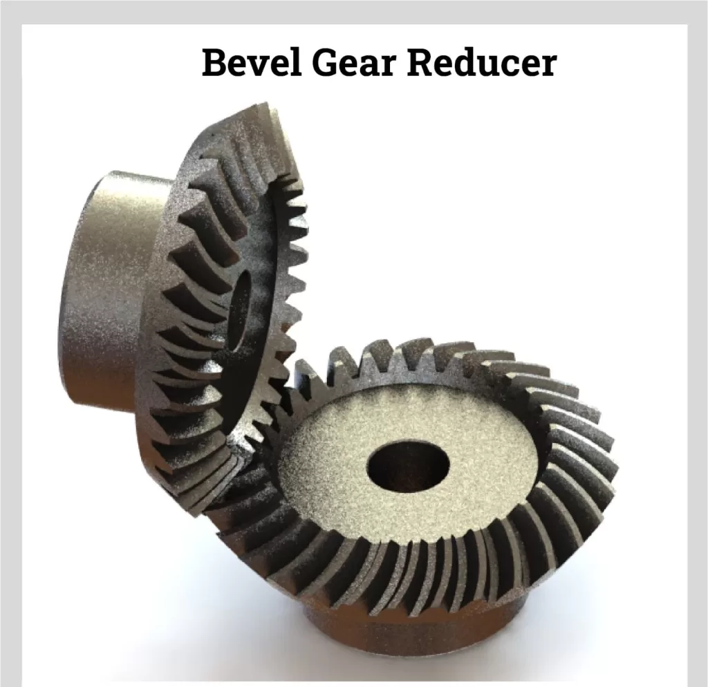
Bevel gears change shaft direction, often by 90 degrees. Bevel-helical combinations can combine right-angle layout with efficient helical stages. Accurate alignment and bearings capable of handling radial and axial gear forces are important.
Spur gear reducers
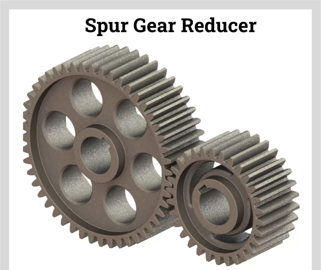
Spur gears have straight teeth and parallel shafts. They are straightforward and can be effective at moderate speeds, though tooth engagement may create more noise than comparable helical designs. They are common in compact machinery and custom gear trains.
| يكتب | Typical strengths | Important tradeoffs |
|---|---|---|
| Helical | Smooth, efficient potential, continuous duty | Axial thrust and multi-stage length |
| Worm | Compact right-angle layout, high single-stage ratio | Heat, sliding losses, application-specific back-driving |
| Planetary | Compact, coaxial, high torque density | Greater design and manufacturing complexity |
| Bevel-helical | Right-angle shaft arrangement with strong efficiency potential | Alignment, axial loads, and package cost |
| Spur | Simple, economical, parallel shafts | Noise and tooth-impact behavior at speed |
Phone users: swipe horizontally to view all table columns.
Gear Reducer vs. Gearmotor
A gear reducer is the mechanical reduction unit. A gearmotor combines a motor and reducer as a matched assembly. An integrated gearmotor can simplify mounting, alignment, and procurement, but the motor and reducer still need to meet the load, speed, thermal, control, and environmental requirements.
When evaluating Faradyi Motor’s gear motor options, compare the loaded output speed and torque—not only motor power or the nominal ratio.
Benefits and Limitations of Gear Reducers
فوائد
- Match a high-speed motor to a slower mechanical load.
- Multiply usable output torque within the reducer rating.
- Change shaft direction or position to fit the machine layout.
- Increase reflected load inertia control in many motion systems.
- Provide compact, repeatable mechanical transmission.
Limitations
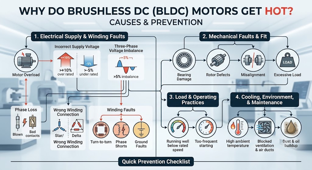
- Efficiency losses produce heat and reduce available output power.
- Backlash and torsional compliance affect positioning and reversal.
- Gears, bearings, seals, and lubricant require correct installation and maintenance.
- The reducer adds mass, package size, noise, and cost.
- Excess shock, misalignment, contamination, or incorrect lubrication can cause premature failure.
How to Select the Right Gear Reducer
- Define the load: continuous, peak, starting, stopping, reversing, shock, and jam torque.
- Calculate ratio: divide required reducer input speed by desired output speed, then verify the actual catalog ratio.
- Apply service factor: use manufacturer guidance for application type, prime mover, hours per day, starts, and shock severity.
- Check mechanical rating: confirm continuous and peak output torque at the required input speed.
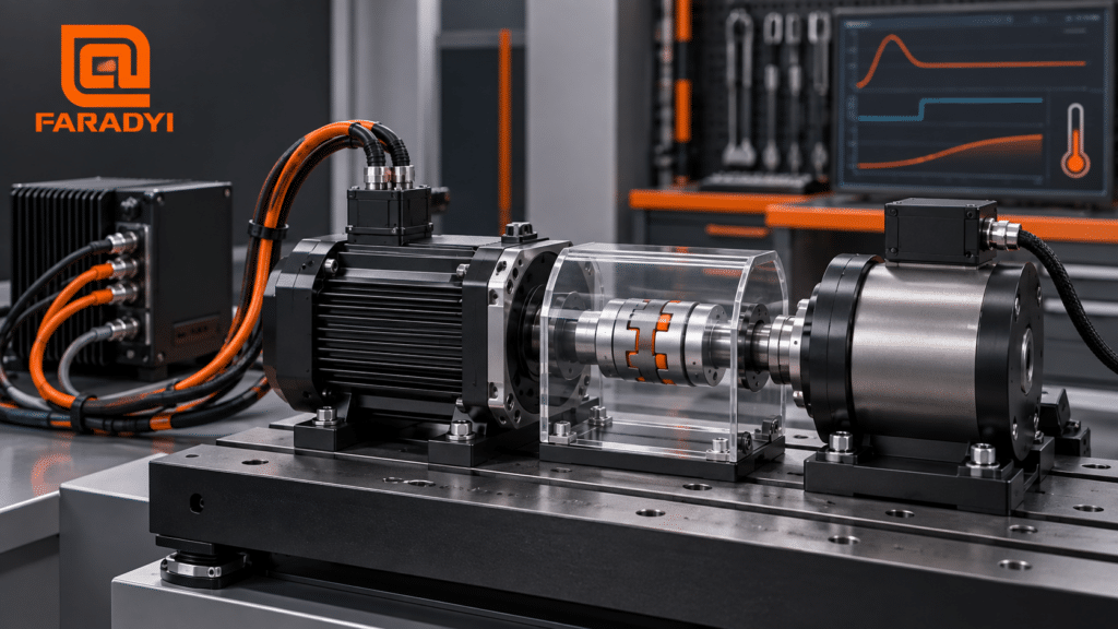
- Check thermal capacity: consider power loss, ambient temperature, duty cycle, enclosure, airflow, and mounting.
- Verify precision: specify backlash, lost motion, torsional stiffness, repeatability, and allowable positioning error.
- Check shaft loads: evaluate coupling, pulley, sprocket, belt or chain forces, lever arm, and axial load.
- Confirm mounting: shaft arrangement, orientation, feet or flange, hollow or solid output, torque arm, and space.
- Define the environment: temperature, washdown, dust, chemicals, corrosion, vibration, altitude, and required protection.
- Validate lubrication and maintenance: approved oil or grease, mounting-dependent fill, intervals, seals, vents, and accessibility.
Installation and Maintenance Essentials
- Mount on a rigid, flat structure and align connected shafts accurately.
- Place pulleys and sprockets close to the housing where practical to reduce overhung load.
- Use the correct lubricant, fill quantity, vent position, and mounting-orientation instructions.
- Inspect for leakage, unusual temperature, vibration, noise, loose fasteners, and contamination.
- Lock out energy and prevent unexpected motion before service.
الأسئلة الشائعة
What is the main purpose of a gear reducer?
Its main purpose is to reduce input speed and increase available output torque while adapting the motor to the load’s mechanical requirements.
Does a 10:1 reducer multiply torque by exactly ten?
Not exactly. The ideal multiplication is ten, but actual output torque is lower because of efficiency losses. It also cannot exceed the reducer’s mechanical or thermal rating.
What is backlash?
Backlash is rotational clearance between mating teeth, often observed when torque direction reverses. It is different from torsional deflection and total lost motion, so precision applications should specify each relevant requirement.
Are worm reducers self-locking?
Some worm sets may resist back-driving under defined conditions, but behavior changes with geometry, lubrication, wear, vibration, and load. Use a rated brake or holding device where safety requires restraint.
How do I know which gear reducer type to use?
Start with shaft arrangement, ratio, torque, duty, efficiency, backlash, thermal capacity, package space, noise, environment, and budget. Then compare manufacturer ratings for the exact operating conditions.
Choose a Gearmotor for Your Application
Well-selected gear reducers make motors more useful by matching speed, torque, and shaft arrangement to the machine. Reliable results come from treating the motor, reducer, drive, coupling, and load as one system.
Review Faradyi gear motors and provide the input voltage, motor control, required output speed, continuous and peak torque, duty cycle, ratio, shaft and mounting arrangement, radial or axial loads, backlash target, environment, brake or feedback needs, and expected quantity.
Technical References