Up until now, the majority of people lack awareness of brushless DC motors and drivers, even though they may have encountered them in everyday appliances like air conditioners, washing machines, electric fans, hairdryers, etc. Due to the lack of exposure to the actual components, it’s normal to have limited knowledge of the entire system.
Let’s delve into the fundamental aspects of brushless DC motor systems.
All motors involve a concept known as “commutation,” referring to the process of switching the current (in a certain way) to move the physical rotor. When current flows through the coil, the rotor moves, creating a magnetic field (typically generated by a permanent magnet). This field may repel or attract the existing magnetic field, leading to motion of the rotor (the moving part of the motor) relative to the stator (the stationary part of the motor).
The concept of magnets serves as a good analogy for commutation. When placing two magnets with the same pole facing each other on a table, they repel each other. If these magnets are far enough apart, they will stop moving. Bringing one magnet closer to the other will push the second magnet away due to the repulsion. Continuing this process results in continuous movement—a linear example of commutation.
Brushed DC motors implement mechanical commutation
meaning the physical structure of the motor causes commutation. Brushes make contact with the commutator, and as the motor rotates, the current passing through the motor coil alternates the polarity. This allows the magnetic field generated by the stator’s permanent magnet to always oppose the magnetic field generated by the rotor, ensuring a continuous force. Mechanical commutation means that a brushed DC motor only requires the application of voltage to the motor windings to rotate.
Many readers might be confused by the title at this point since I haven’t discussed brushless DC motors yet. However, to explain “brushless,” I first need to clarify where brushes are used.
The origin of brushless DC motors is relatively straightforward:
most problems with brushed DC motors arise from the brushes. Brushes can create sparks, wear out, generate loud noises, and contribute to significant power consumption, restricting speed and making cooling difficult. This means brushed DC motors are not suitable for applications around flammable materials, requiring a long lifespan, quiet operation, or high efficiency in high-speed or high-power systems. These are significant drawbacks of brushes, which can be addressed by eliminating them, but this also removes mechanical commutation.
The absence of mechanical commutation introduces other issues
As motors still need commutation. Brushless DC motors use electrical commutation, sounding like magic, right? In this method, you must ensure that the current in the motor consistently generates a magnetic field capable of moving the rotor. You need to know where the rotor is to consider how to apply the current to move it.
The first major structural decision in brushless DC motor systems is the distinction between “sensored” and “sensorless” systems.
If you need to know where the rotor is, two methods can help you:
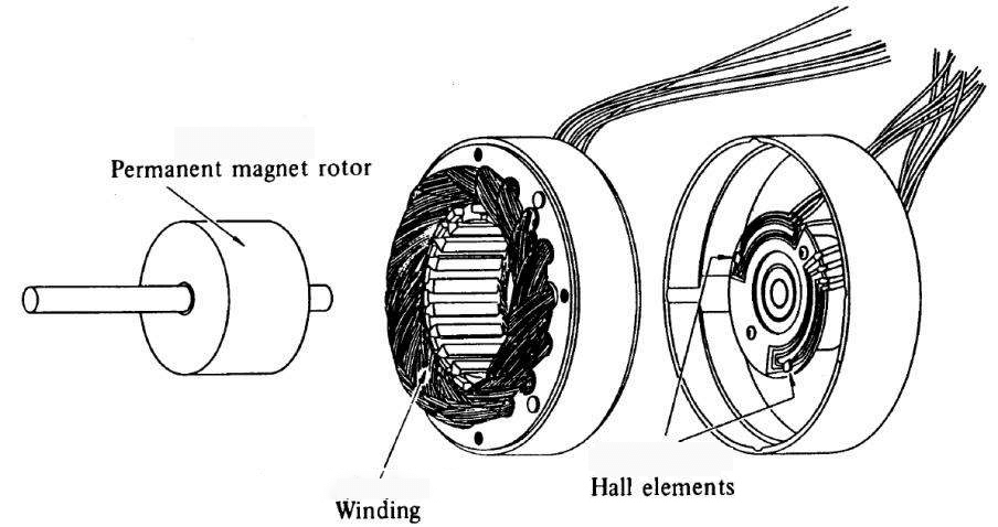
- Sensored methods typically use Hall effect sensors or encoders to detect the rotor’s position. While encoders can provide very accurate angle feedback, this method comes at a high cost. The Hall effect sensor is a popular magnetic sensor, and in three-phase brushless DC motors, deploying three Hall effect sensors can achieve simple six-step commutation.
- Sensorless methods involve estimating the back electromotive force (EMF) generated when the motor rotates. Back EMF is a complex topic best discussed separately. In short, it is the voltage generated on the motor coil, a function of motor speed and load. Sensorless methods are essentially estimates, often requiring intricate calculations. As motor speed decreases (e.g., for position control in servo motors), sensorless methods become exceptionally challenging due to the decreasing back EMF.
The second major structural decision in brushless DC motor systems is the control method.
If you know where the rotor is and need to apply a certain current to move it, three-phase brushless DC motors require at least six different electrical potentials. You can use “trapezoidal,” “six-step,” or “120-degree” control methods to determine how to commutate the brushless DC motor.
- Trapezoidal commutation
- Sinusoidal commutation
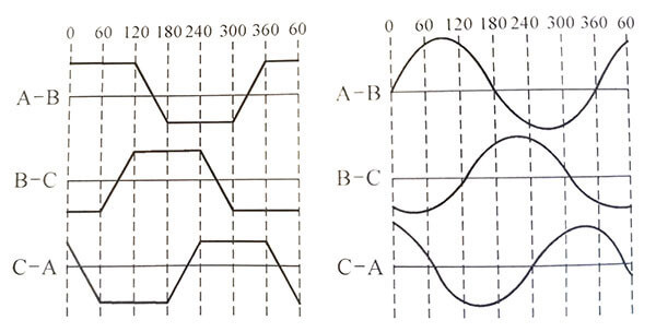
Another method is to apply smoother current waveforms to the motor, known as “sinusoidal” control or “180-degree” control.
This control method can improve efficiency and reduce noise when used with the right motor, but it comes with higher complexity, often requiring more precise pulse-width modulation (PWM) timing.
The above content provides a brief introduction to the basic knowledge of brushless DC motor systems. Due to the broad nature of the topic, details such as magnetic field orientation control, motor startup, inner and outer rotors, pole numbers, Δ (Delta) and Y-type windings, and many other specifics are not covered in this article. However, it is sincerely hoped that you find this information beneficial in expanding your knowledge of motors.
Dongguan Faradyi Motors Co., Ltd. specializes in the global industrial automation field, focusing on the research and development of high-performance, high-quality brushless DC motors, DC servo motors, stepper motors, and related drive controllers, making it a leading domestic high-tech enterprise in motion control technology solutions.