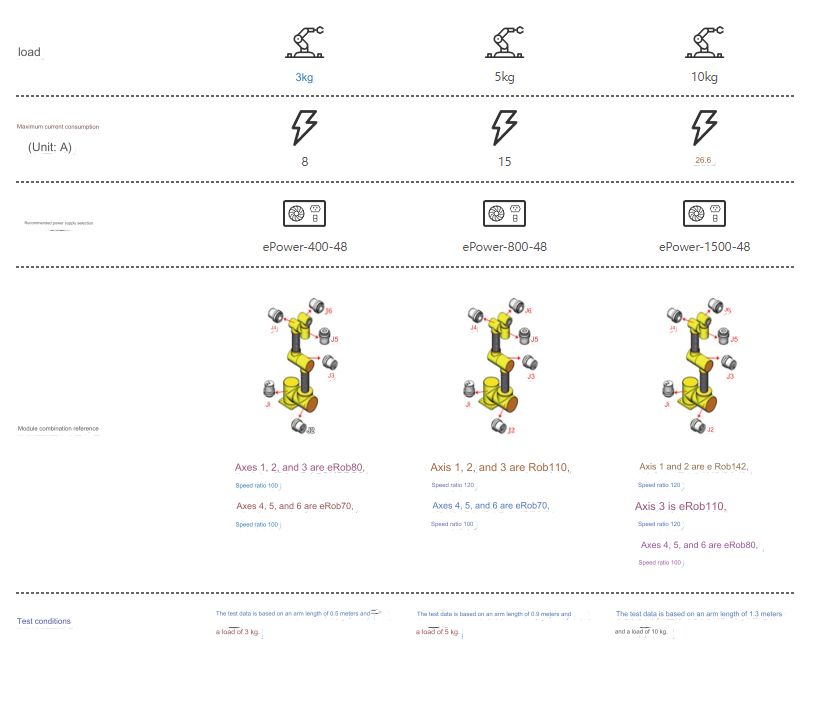
Frequently Asked Questions

Common Issues with Robot Joints:

Robot Power Consumption Meter.

Robot Power Consumption Meter.

For a collaborative robot with a payload of 3 kilograms, the maximum power consumption current is 8A, and the recommended power supply is ePower-400-48.

For a collaborative robot with a payload of 5 kilograms, the maximum power consumption current is 15A, and the recommended power supply is ePower-800-48.

For a collaborative robot with a payload of 10 kilograms, the maximum power consumption current is 26.6A, and the recommended power supply is ePower-1500-48.

Joint Accessories:
– For multi-turn joints, an additional 3.6V multi-turn battery is included compared to single-turn joint accessories.

Counting Functionality:
– Multi-turn joints support multi-turn counting functionality for feedback at the load end. Single-turn joints only support multi-turn counting functionality at the load end when the joint is not powered off.

Position Feedback:
– For multi-turn joints, the position feedback remains consistent before and after power-off. For single-turn joints, the multi-turn value is lost after power-off.

Installation and Use:
– Before using multi-turn joints, connect the 3.6V multi-turn battery and then clear any battery-related errors. For single-turn joints, adjustments to the joint output end position are needed before installation.

What is the accuracy of the robot joints?

 Precision measurement video of eRob joint at customer site

Faradyi Control eRob joint, the measured operational noise is only around 55 decibels at 30 RPM and around 62 decibels at 60 RPM.

Root Cause Analysis: Motion range is restricted by parameter settings.

Recommended Actions:

  1. Check the position limit settings on the safety position interface. Ensure that the target position does not exceed the set position limit range.

  2. Check the “Motion” interface to see if the application acceleration and deceleration limits for all movements are selected. If selected, deselect them.

  3. Verify that the parameters for the position filter on the “PID Settings” interface are set correctly.

Error Prompt:
1. Bus voltage is lower than the minimum allowed voltage setting.

Root Cause Analysis:
1. Detection of main circuit power voltage below the threshold.
2. Voltage drop due to a momentary power outage with lower power supply voltage.
3. Insufficient power supply capacity leading to a decrease in voltage due to the sudden current surge when the main power is turned on.
4. Servo drive failure (circuit malfunction).

Recommended Actions:
1. Measure the voltage at the power supply terminal to ensure the correct input voltage.
2. Confirm whether the minimum allowed bus voltage setting is reasonable.
3. Increase the capacity of the power supply voltage. Change the power supply, eliminate the possibility of the electromagnetic contactor disconnecting the main power, and then restore power.
4. Optimize the bus wiring method (when multiple modules share one power supply, refer to the joint manual for power wiring methods).
5. Replace with a new drive.

Error Prompt:

  1. Bus voltage is higher than the maximum allowed voltage setting.

Root Cause Analysis:

  1. Detection of main circuit power voltage exceeding the threshold.
  2. Power supply voltage is too high.
  3. The maximum allowed bus voltage setting is too small.
  4. Significant kinetic energy feedback during deceleration work or movement in the direction of gravitational force.
  5. Servo drive failure (circuit malfunction).

Recommended Actions:

  1. Measure the voltage at the power supply terminal to ensure the correct input voltage.
  2. Confirm whether the maximum allowed bus voltage setting is reasonable.
  3. Increase the discharge resistance or use a supercapacitor for absorption (refer to the joint manual for regenerative energy handling).
  4. Replace with a new drive.

Error Prompt:

  1. Phase U current exceeds the allowed current peak value.
  2. Phase V current exceeds the allowed current peak value.
  3. Phase W current exceeds the allowed current peak value.

Root Cause Analysis:

  1. Current in each phase exceeds the maximum threshold for a single-phase current.
  2. Motor malfunction, inter-turn or inter-phase short circuit, local insulation degradation.

Recommended Actions:

  1. Verify if there is a short circuit in the motor connections U, V, W or if there are burrs on the wires at the connector end. Correctly connect the motor wires.
  2. Replace with a new motor.

Error Prompt:

  1. Trigger maximum current (cut-off).
  2. Current flowing through the rectifier exceeds the threshold.

Root Cause Analysis:

  1. Drive failure (circuit, IGBT, etc., defective components).
  2. Motor lines U, V, W short circuit.
  3. Motor burnout.
  4. Poor contact of motor lines.
  5. Relay malfunction in the dynamic brake due to frequent servo enable ON/OFF.
  6. The maximum current setting value is too small.

Recommended Actions:

  1. Disconnect the motor lines, enable the servo, and if the fault occurs immediately, replace the servo drive with a new one (while in operation).
  2. Verify if there is a short circuit in the motor connections U, V, W or if there are burrs on the wires at the connector end. Correctly connect the motor wires.
  3. Confirm the balance of the resistance between the motor’s various lines. If unbalanced, replace the motor.
  4. Verify if the connectors of each phase U, V, W of the motor are loose; if loose or detached, secure them.
  5. Replace the servo drive. Stop actions under servo enable ON/OFF.
  6. Increase the maximum current setting value.

Error Prompt:

  1. Motor 3-phase current and error.
  2. Detection of motor three-phase current and error exceeding the threshold.

Root Cause Analysis:

  1. Motor wiring error, disconnection.
  2. Overloaded load, overshock (mechanical collisions, sudden mechanical weight increase, mechanical distortion).
  3. Motor malfunction, inter-turn or inter-phase short circuit, local insulation degradation.
  4. Servo drive failure (current sampling circuit malfunction).
  5. Motor three-phase current and setting value are too small.

Recommended Actions:

  1. Correctly connect the motor phases (U, V, W).
  2. Reduce the load, eliminate mechanical faults (stiff lubricating oil, bearing jamming, mechanical rust, etc.).
  3. Replace with a new motor.
  4. Replace with a new drive.
  5. Increase the motor three-phase current and setting value.
 

Root Cause Analysis:

  1. Insufficient voltage in the multi-turn battery.
  2. Battery connection line is disconnected.

Recommended Actions:

  1. Replace the battery in the multi-turn encoder.
  2. Check the connections of the battery in the load.
  3. Reset the multi-turn encoder in the load.

Root Cause Analysis:

  1. Motor current is greater than the stall current, and motor speed is lower than the stall speed, lasting longer than the stall time.
  2. Overloaded load.
  3. Mechanical faults (bearing jamming, mechanical rust, mechanical distortion, foreign object obstruction, etc.).

Recommended Actions:

  1. Confirm whether the continuous current, peak current, and stall parameters are set reasonably.
  2. Reduce the load.
  3. Eliminate mechanical faults (stiff lubricating oil, bearing jamming, mechanical rust, mechanical distortion, foreign object obstruction, etc.).

Root Cause Analysis:

  1. Actual position deviation exceeds the set threshold for the maximum allowed position error.
  2. Motor does not follow the commanded motion.
  3. The set value for the maximum allowed position error is too small.

Recommended Actions:

  1. Avoid excessively large position commands.
  2. Confirm whether the motor rotates following position commands. Adjust gains, follow encoder wiring according to the wiring diagram, extend acceleration/deceleration time, reduce load, and decrease speed.
  3. Increase the set value for the maximum allowed position error.

Root Cause Analysis:

  1. The difference between internal position command speed and actual speed (velocity deviation) exceeds the set maximum allowable speed error.
  2. Overloaded load.
  3. Mechanical faults (bearing jamming, mechanical rust, mechanical distortion, foreign object obstruction, etc.).

Note: Because the internal position command speed also increases the velocity deviation during startup, ensure an adequate margin.

Recommended Actions:

  1. Avoid excessively large velocity commands.
  2. Extend the acceleration/deceleration time of the internal position command speed or improve tracking by increasing gains.
  3. Increase the set value for the maximum allowable speed error.
  4. Reduce the load.
  5. Eliminate mechanical faults (stiff lubricating oil, bearing jamming, mechanical rust, mechanical distortion, foreign object obstruction, etc.).
 

Root Cause Analysis: The motor speed exceeds the set value for the maximum allowable speed.

Recommended Actions:

  1. Avoid excessively large speed commands.
  2. If overshooting occurs due to poor gain adjustment, readjust the gains.
  3. Follow the encoder wiring according to the wiring diagram.

Rated Torque: Rated torque represents the allowable continuous load torque when the input speed is 2000 revolutions per minute (r/min).

Start-Stop Peak Torque: Start-stop peak torque is the torque that occurs during the start and stop phases. Due to the load’s rotational inertia, there can be a torque applied to the joint module that is greater than the normal torque.

Single-turn Encoder: For joint modules with a single-turn encoder, it is necessary to adjust the output end position before installation. This ensures that within the operational range of the device, there will be no overshooting of the single-turn encoder boundary positions (0 and 524287). Otherwise, there may be a loss of multi-turn counting during power-off restart, and the joint position feedback will become the single-turn position of the output end encoder.

Multi-turn Encoder: For joint modules configured with a multi-turn encoder, there is no need to adjust the output end position before installation. However, it is necessary to install a 3.6V multi-turn power supply battery before use. Afterward, click the reset load-end encoder button on the upper computer encoder interface to clear the multi-turn battery error. If a multi-turn joint is not connected to a battery, it will still result in an error after the next power-off restart, and multi-turn counting will be lost (i.e., the position feedback will become the single-turn position of the output end encoder).

Calculation Method for Maximum Load Static Moment (Mmax):

Please confirm Mmax ≤ Mc (See formula symbols in Table 1-2).

Table 1-1 Explanation of Formula Symbols:

  • Frmax: Maximum radial load (N or kgf) – Refer to the external load diagram.
  • Famax: Maximum axial load (N or kgf) – Refer to the external load diagram.
  • Lr, La: __ (unit not specified, possibly meters) – Refer to the external load diagram.
  • R: Offset (m) – Refer to the external load diagram in the specifications table for each series.
ncom

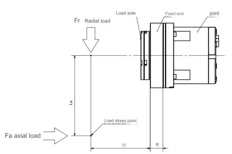
Table 1-2 Allowable Torque Values for Each Joint Type:

Joint Type Offset (R) Allowable Torque Load (Mc)
eRob70 0.0217m 74 Nm / 7.6 Kgfm
eRob80 0.0239m 124 Nm / 12.6 Kgfm
eRob90 0.0255m 187 Nm / 19.1 Kgfm
eRob110 0.0296m 258 Nm / 26.3 Kgfm
eRob142 0.0364m 580 Nm / 59.1 Kgfm
eRob170 0.044m 849 Nm / 86.6 Kgfm

Example: Given the selection of the eRob70H joint with La = 0.2m, Lr = 0.5m, Frmax = 50N, and Famax = 30N.

From Table 1-2, R = 0.0217m, Mc = 74 Nm.

Substitute into the formula:

Since , it satisfies the bending torque requirements.
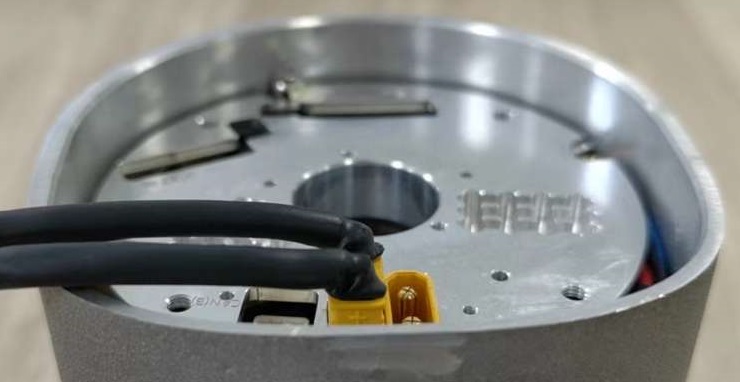
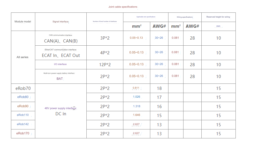
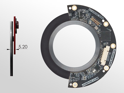
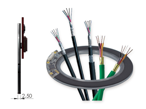
Power supply wiring example

Power supply wiring example

Joint Cable Specifications:

Joint Cable Specifications:

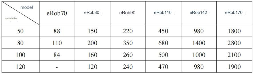
In a robot joint module, when subjected to an excessive impact torque during operation, the engagement between the rigid wheel and the flexible wheel gears may momentarily shift, even if the components such as the gearbox flex spline remain undamaged. This phenomenon is referred to as “backlash.” The torque during this occurrence is known as backlash torque (refer to the values in the table below). If the backlash phenomenon persists during operation, the generated wear particles from backlash can lead to early gear wear, thereby reducing the service life of the harmonic drive bearings.

Backlash Torque Values

It’s crucial to address and mitigate backlash issues promptly to prevent prolonged operation under such conditions, minimizing the impact on gear longevity and harmonic drive bearing performance.

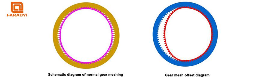
The normal meshing of gears is shown in the lower left diagram. When a dog is engaged, the gears may mesh abnormally, as depicted in the lower right diagram, with a single-sided offset. Continuing operation in this state can result in vibrations, leading to damage to the flexible gear.

Gear mesh diagram

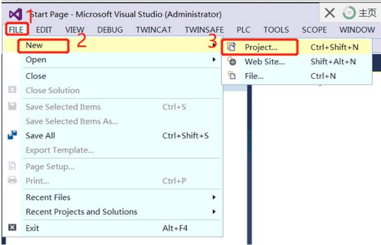
1. As shown in Figure 1, open the menu bar File->New->Project and create a new TwinCAT project.

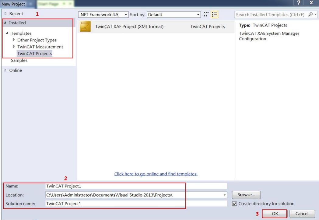
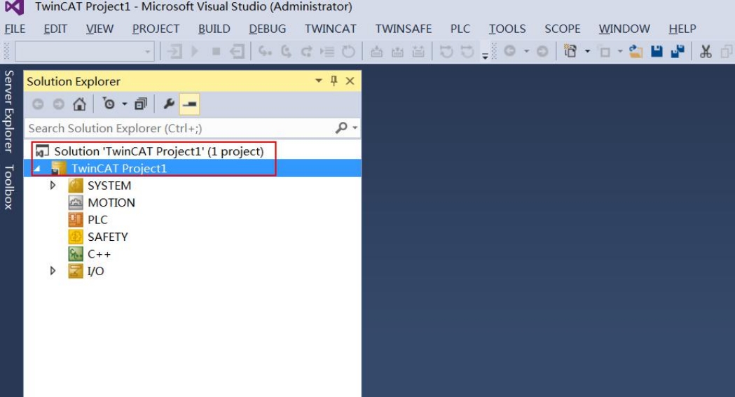
2. The New Project window pops up (as shown in Figure 2), select Installed->Templates->TwinCAT Projects on the right, name the project in English (Name), select the project storage path (Location), and click the “OK” button to create a new A project named “TwinCAT Project1” was created (Figure 3).

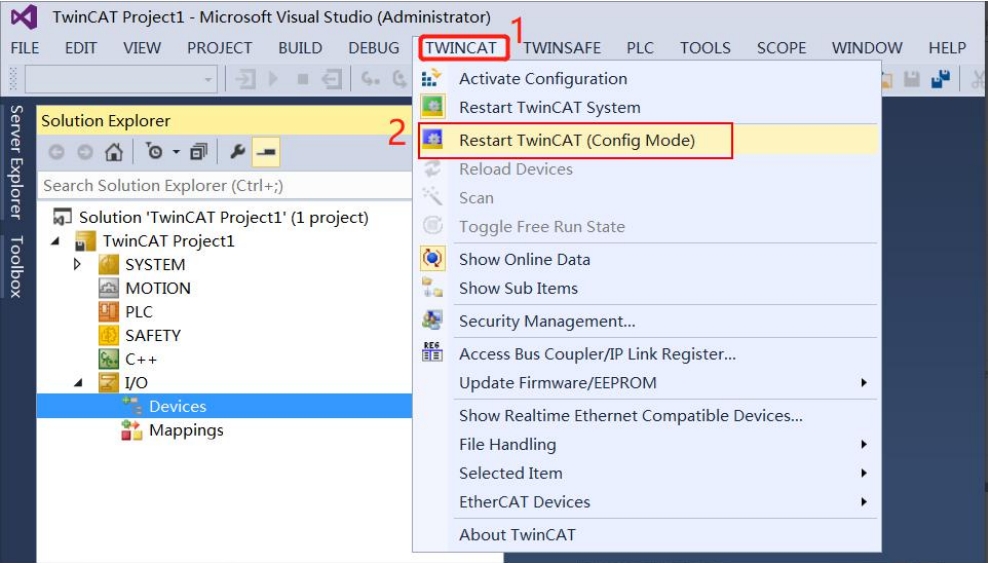
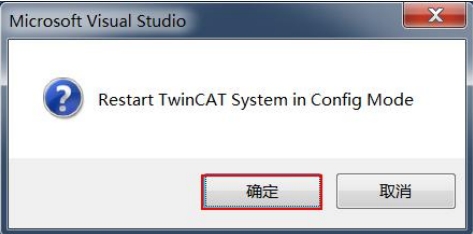
3. As shown in Figure 4, click TwinCAT->Restart TwinCAT (Config Mode) in the menu bar. The Microsoft Viusal Studio window will pop up (Figure 5), and click the “OK” button.

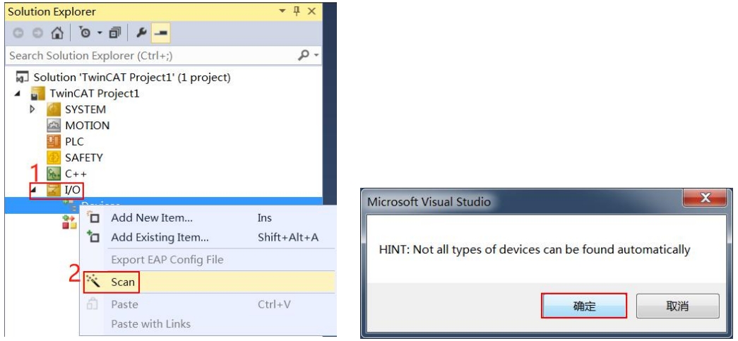
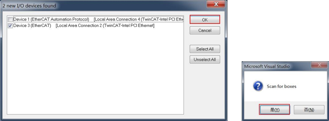
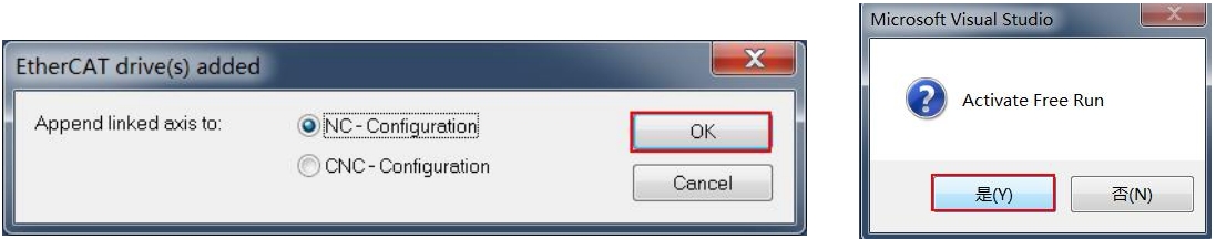
4. As shown in Figure 6, select I/O in the project directory, right-click Devices->Scan, the Microsoft Viusal Studio window will pop up (as shown in Figure 7), and click the “OK” button. The “new I/O devices found” window pops up (as shown in Figure 8), and the automatically selected device is the scanned slave device (if the automatically selected device is not displayed, it means that the slave device has not been scanned, and the device needs to be confirmed. running status and network cable connection are normal), click the “OK” button. Just click the “OK” or “Yes” button in subsequent pop-up windows (Figure 9~Figure 11).

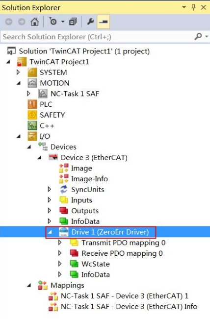
5. At this point, as shown in Figure 12, the ZeroErr Driver logo icon and the slave device name Drive1 (Zerror Driver) appear under the IO/Devices path of the “TwinCAT Project1” project, indicating that the master station successfully scanned and connected the servo driver, otherwise the servo drive needs to be confirmed. Whether the corresponding XML file and its placement path are correct.

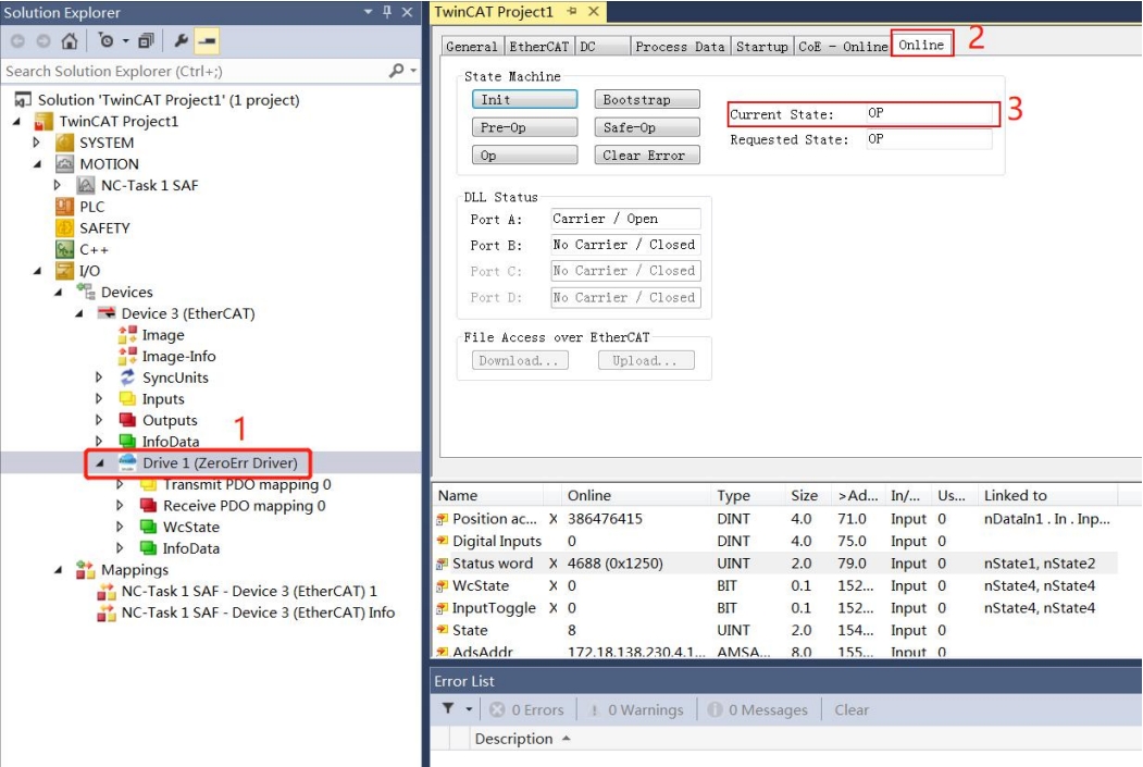
6. As shown in Figure 13, click the device name Drive1 (Zerror Driver), click “Online” to view the state machine status of EtherCAT. If the Current State displays “OP”, it means the driver enters OP mode normally.
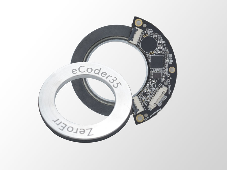


Encoder Common Issues:

The principle of a magnetic encoder is similar to that of an optical encoder, but it utilizes magnetic field signals. Inside the magnetic encoder, there is a magnetic disc and a magnetoresistive sensor. The rotation of the magnetic disc causes a change in the internal magnetic field strength, which is detected by the magnetoresistive sensor. The signal is then processed through the circuit to generate the output signal. The resolution of the magnetic encoder is determined by the number of magnetic poles on the magnetic disc, the quantity of magnetoresistive sensors, and the signal processing method. One advantage of using magnetic field principles for signal generation is that magnetic signals are not affected by dust, humidity, high temperatures, or vibrations.

ecoder

Compared to traditional optical and grating encoders, magnetic encoders have superior characteristics such as vibration resistance, corrosion resistance, pollution resistance, interference resistance, and a wide temperature range. They can be applied in fields where traditional optical encoders may not be suitable. The Faradyi Motors encoder series remains applicable in harsh environments such as oil-contaminated areas, high vibration environments, high humidity, and extreme temperature conditions. Magnetic encoders are specifically designed for extreme and challenging environments that demand broad temperature characteristics, resistance to intense vibration and impact, and high protection levels.

Furthermore, our magnetic encoders feature reliable signal output circuits, simple installation methods, and can significantly reduce downtime losses. Typically used in metallurgy, papermaking, and woodworking machinery, high-performance magnetic encoders find extensive applications in industrial control, mechanical manufacturing, ships, textiles, printing, radar, communication, and other fields.

Faradyi Motors independently designs and produces magnetic encoders. Our magnetic encoders are known for their simple and compact structure, no contact points, long lifespan, resistance to high and low temperatures, vibration resistance, quick response speed, and resilience to the effects of dust and condensation. They are widely utilized by customers in areas such as robotics, automated production lines, assembly machines, elevators, textile machinery, sewing machines, packaging and printing machinery, CNC machine tools, plotters, angle measuring instruments, and more.

From Single-Turn Absolute Encoder to Multi-Turn Absolute Encoder.

Rotary single-turn absolute encoders read the position of the magnetic code disc during rotation to obtain a unique code. When the rotation exceeds 360 degrees, the code returns to the starting point. This does not adhere to the principle of unique absolute encoding, and such encoding can only be used for measurements within a rotation range of 360 degrees, known as a single-turn absolute encoder.

Faradyi Multi-Turn Rotary Encoder

For measurements that exceed a rotation range of 360 degrees, multi-turn absolute encoders are required. These encoders build upon single-turn encoding by adding additional turns to expand the measurement range. Such absolute encoders are known as multi-turn absolute encoders. Similar to single-turn encoders, they determine the mechanical position of the code, ensuring that each position code is unique and non-repeating without the need for memory.

Another advantage of multi-turn encoders is their larger measurement range, providing redundancy. This redundancy simplifies installation and eliminates the need to find the zero point precisely during setup. Choosing any intermediate position as the starting point is sufficient, significantly simplifying the installation and debugging process.

Faradyi encoders offer resolutions of up to 23 bits and 2^40 revolutions, along with programmable and stored point-to-point position compensation. This technology achieves unprecedented encoder accuracy of ±2.5 arcseconds.

An encoder refers to a device that encodes signals or data, converting them into signals that can be used for communication, transmission, and storage. It can be classified into two main types: incremental and absolute encoders, with wide applications in our production and daily life.

eCoder35H_2

Classification of Encoders:

  1. Incremental Encoder: Incremental encoders utilize the photoelectric conversion principle to output three sets of square wave pulses—A, B, and Z phases. The A and B pulse phases have a 90-degree phase difference, allowing for easy determination of the rotation direction. The Z phase provides a pulse for each full revolution, serving as a reference point for positioning. Its advantages include a simple construction principle, mechanical lifespan exceeding tens of thousands of hours, strong anti-interference ability, high reliability, and suitability for long-distance transmission. However, it cannot output the absolute position information of the shaft’s rotation.

  2. Absolute Encoder: Absolute encoders directly output digital signals. Whether in industrial environments or harsh outdoor applications, enhancing efficiency, reliability, and durability is crucial. Therefore, encoder components must meet various requirements while ensuring maximum durability and higher cost-effectiveness. The eCoder series magnetic absolute multi-turn encoders introduced by ZeroDifference Cloud Control have passed tests under the world’s harshest environmental conditions. These encoders combine reliable robustness, ultra-high precision, and advanced communication technology, opening up a wide range of highly attractive application areas.

  3. Hybrid Absolute Encoder: The hybrid absolute encoder outputs two sets of information: one set for detecting magnetic pole positions with absolute information functionality, and the other set identical to the output information of incremental encoders.

eCoder45_1

Faradyi Hollow Encoders feature a maximum diameter center hole of up to 83mm, allowing them to easily pass through mechanical structures, cables, pneumatic systems, and more.

Faradyi Hollow Encoders

With an ultra-thin design and fixation or locking by spring plates, these encoders require no additional accessories during installation. They also provide shock absorption, ensuring coaxiality. Widely used in applications demanding high precision and compact spaces, they are particularly suitable for use with DC direct-drive motors.

Customizable precision support hubs facilitate quick and precise installation.

When combined with Faradyi Motors miniature embedded drives, they enable compact servo control.

Applications include medical equipment, robot joints, general automation, and DD motor machine tools, among other fields.

Absolute value encoders provide a complete positional output in terms of position points, comprising both multi-turn and single-turn data. The reference point is the absolute zero point of the encoder (configurable by the user).

It’s important to note that the multi-turn value is a 16-bit signed data, while the single-turn value is unsigned data. The calculation formula is as follows:

Encoder rotation angle (°) = (Encoder full position output value / Single-turn resolution) * 360 (°);

The absolute value encoder’s full position output is in position points, consisting of multi-turn and single-turn data. For example, if a user sends the command 0x1A via 485:

Encoder response to 0x1A, 0x00, 0x6b, 0xf6, 0x11, 0x15, 0x06, 0x00, 0x00, 0x00, 0x84; then the single-turn value is 0x11f66b, and the multi-turn value is 0x000006.

The encoder’s full position output value is calculated as 0x000006 * (resolution) + 0x11f66b.

Physical Damage:

  1. During installation, improper operations, falls, impacts, etc., can result in scratches, scrapes, or even fractures on the encoder disk.
  2. Abnormal external forces on the motor shaft can cause the encoder disk to shift with the shaft, leading to friction and wear against the magnetic surface.

Chemical Exposure: No Impact: Motor oil, hydraulic (brake) oil, kerosene, antifreeze, detergents, turpentine, water, saltwater.

Avoid Contact: Gasoline spray, alcohol, heptane.

Prohibited Contact: Aromatic hydrocarbons (benzene, toluene, xylene), ketones, mineral acids (HCl, H2SO4).

Installation Methods: The installation can be done through interference fit or adhesive installation with clearance.

Incremental Encoder: Installation Notes:

  1. Strictly avoid striking, hitting, or collisions during installation to prevent damage to the read head and encoder disk.
  2. Gently push the encoder into the shaft sleeve during installation, strictly avoiding the use of a hammer to prevent damage to the read head and encoder disk.

Installation Accuracy Requirements:

  • Maximum Height Installation Error: <0.2mm
  • Maximum Radial Installation Error: <0.2mm
  • Maximum Concentricity Installation Error: <0.05mm

The concentricity error of the encoder disk has the highest impact on encoder accuracy. Higher concentricity contributes to further improving encoder accuracy.

Electrical Aspects:

  1. The output wires of the encoder should not be connected to each other to avoid damage to the output circuit.
  2. The signal wires of the encoder should not be connected to a DC power source or AC current to prevent damage to the output circuit.
  3. Devices such as motors connected to the encoder should be well grounded to prevent static electricity.
  4. Shielded cables should be used for wiring.
  5. Before powering on, carefully check if the product specifications match the encoder model and if the wiring is correct.
  6. For long-distance transmission, consider signal attenuation factors and choose an output method with low output impedance and strong anti-interference capability.
  7. Avoid use in environments with strong electromagnetic waves.

Precautions for Encoder Usage:

  1. Keep Away from Magnetic Materials:

    • Avoid bringing the magnetic portion of the encoder disk close to materials with a magnetic field to prevent damage to the magnetic tracks on the encoder disk.
  2. Avoid Exposure to Magnetic Fields:

    • Do not expose the magnetic portion of the encoder disk to a magnetic field with a surface intensity greater than 20mT, as this could result in permanent damage to the encoder disk.
  3. Avoid Impact on the Magnetic Ring:

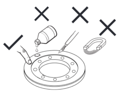
    • During installation or storage of the encoder disk, be careful not to impact the surface where the magnetic ring is located. Ensure that the magnetic ring is not scratched. Do not use corrosive liquids to clean the encoder disk. If there are debris on the surface, gently remove them using a traceless paper tape.
  4. Protect the Read Head:

    • Take precautions to protect the read head to avoid the risk of iron filings falling directly onto it, as this could damage the components.
  5. Static Electricity Awareness:

    • The read head is sensitive to static electricity. Without proper electrostatic protection or in an uncontrolled environment, do not touch the electronic circuits, wires, or sensor areas directly with hands.
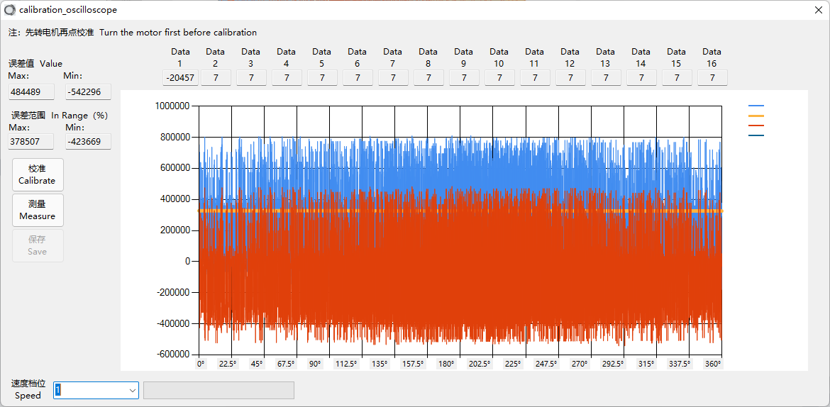
wendaeCoder

Calibration Failure: Common Scenarios

  1. Overall Error Exceeds Tolerance:

wucha1

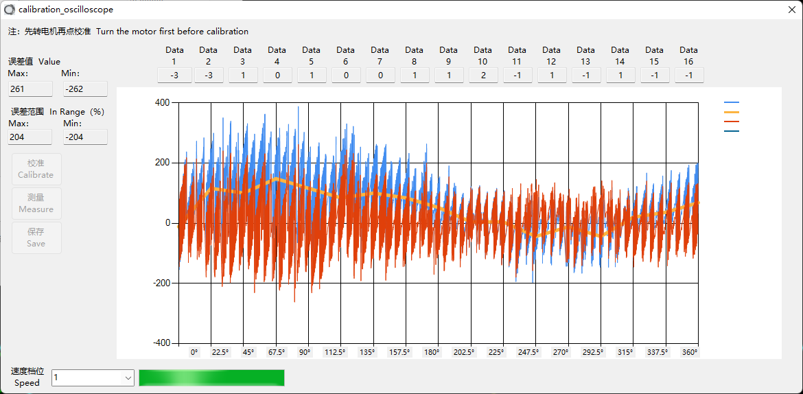
Generally, this waveform occurs due to structural installation. Check or readjust the installation distance between the read head and the code disk. Refer to the mechanical installation instructions.

2. Possible causes for the waveform spikes:

wucha2

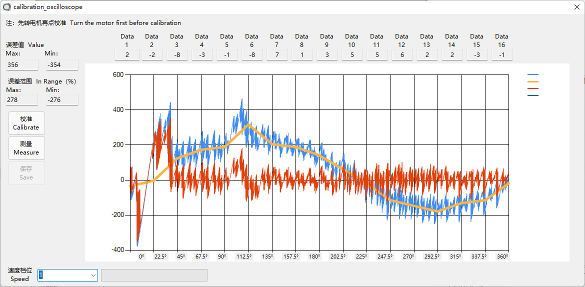
3. Possible causes for abnormal waveforms:

Possible causes for abnormal waveforms:

Analysis and troubleshooting for the given situation:

When encountering such a scenario, the following steps can be taken to analyze and identify potential issues:

  1. Check Power Supply:

    • Verify if the power supply meets the voltage requirements specified for the encoder. Ensure that the supplied voltage is within the acceptable range.
  2. Inspect Encoder and Disc for Stability:

    • Examine the encoder and encoder disc for any jitter or instability during rotation. Ensure that all components are securely fastened and properly fixed.
  3. Review Installation Distance:

    • Evaluate the installation distance between the reader head and the encoder disc. Confirm that the distance is within the recommended range and is not excessively distant.
  4. Inspect Encoder Disc for Damage:

    • Check the encoder disc’s magnetic tracks for any signs of damage. Damage to the magnetic tracks can lead to irregularities in the waveform. Ensure that the encoder disc is free from scratches, cracks, or other forms of damage.

Addressing these aspects should help in identifying and resolving issues associated with the observed abnormal waveform. If the problem persists, additional detailed information about the system configuration and waveform characteristics would be valuable for further analysis.

Error Code 0x730F (Low Battery Voltage) Troubleshooting Guide:

Error code 0x730F indicates a low battery voltage issue in the multi-turn joint encoder. This error is reported through object index 603Fh and cannot be suppressed. It is crucial to address this error promptly to ensure the proper functioning of the joint module. Follow the steps below for troubleshooting:

  1. Installation of 3.6V Multi-Turn Battery:

    • Before using the joint module with a multi-turn encoder, ensure that a 3.6V multi-turn battery is installed.
    • Connect the servo upper computer software (eTunner_V13.50) and open the encoder interface.
    • Click the “Reset Load-Side Encoder” button to clear the error.
    • Alternatively, use the EtherCAT/CANopen bus to write ‘1’ to object index 2242h to clear the error.
  2. User Manual Reference:

    • Refer to the user manual for the joint module (version 3.14) for detailed instructions on using the multi-turn functionality and handling battery-related errors.
    • Pay special attention to section 10.4 (“Joint Positions and Precautions for Using Multi-Turn Functionality”) and section 11.4 (“Handling of Battery-Related Errors”).
  3. Handling Low Battery Voltage Errors (0x730F):

    • If the multi-turn joint is not connected to the battery or the battery voltage is low, the encoder may lose multi-turn data and trigger error 0x730F.
    • Follow the instructions in the user manual to address low battery voltage issues, which may involve replacing the battery and performing the correct reset operation.
  4. Other Possible Causes:

    • Check for correct battery usage, ensuring that the right type of battery is used.
    • Inspect the battery circuit for any abnormalities that may lead to rapid consumption.
  5. Further Troubleshooting:

    • If the error persists, consider consulting technical support or the manufacturer for additional guidance.
    • Ensure that all steps outlined in the user manual are followed accurately.

Addressing these points systematically should help resolve the low battery voltage error (0x730F) in the multi-turn joint encoder.

Troubleshooting Guide for Changes in Single-Turn Position After Reboot:

If the single-turn position undergoes changes after a reboot, it could be due to installation errors exceeding basic requirements or calibration anomalies (uncalibrated or calibration errors > 90%). Follow the steps below to assess and address the issue:

  1. Check for Regular Jumps:

    • Observe if there are regular and systematic jumps in the single-turn position.
    • For eCoder models 11/18/20, expect jumps of approximately 11°, and for eCoder 35/45/65, jumps of around 5°.
  2. Calculate Jump Range:

    • Calculate the jump range using the formula: (117167 - 108981) / 524288 * 360 ≈ 5.6°.
    • Verify if the observed jumps fall within the expected range, indicating regular patterns.
  3. Use eCoder Serialport Tool:

    • Utilize the eCoder_Serialport_Tool_V1.8_3.5 software (available on the official website).
    • Reperform the calibration process using the software.
    • If calibration errors exceed 90%, inspect the installation of the reading head and code disc for compliance with basic requirements. Refer to the encoder manual “Faradyi_eCoder_Manual_Ver1.7,” Chapter 3, for installation requirements.
  4. Re-Calibration After Ensuring Installation Compliance:

    • After confirming that the installation meets basic requirements, redo the calibration process.

By following these steps, you can identify and address issues related to changes in the single-turn position after a reboot. Regular calibration and adherence to installation requirements are crucial for maintaining accurate encoder readings.

Order General Question:

Send Us Inquiry → Receive Our Quotation → Negotiate Details → Confirm The Sample → Sign Contract/deposit →mass Production →cargo Ready → Balance/delivery → Further Cooperation

Sample Is Available For You. Please Contact Us For Details. Once We Charge You Sample Fee, Please Feel Easy, It Would Be Refund When You Place Formal Order.

Dhl, Ups, Fedex, Tnt, Ems, China Post,sea Are Available. The Other Shipping Ways Are Also Available, Please Contact Us If You Need Ship By The Other Shipping Way.

Deliver Time Depends On The Quantity You Order. Usually It Takes 15-25 Working Days.

Please Contact Our Support Team And We Will Confirm Your Order With The Package Contents.we Apologize For Anyinconveniences.

We Accept Payment By T/T, Paypal, The Other Payment Ways Also Could Be accepted,please Contact Us Before You Pay By The Other Payment Ways. Also 30-50% Deposit Is Available, The Balance Money Should Be Paid Before Shipping.