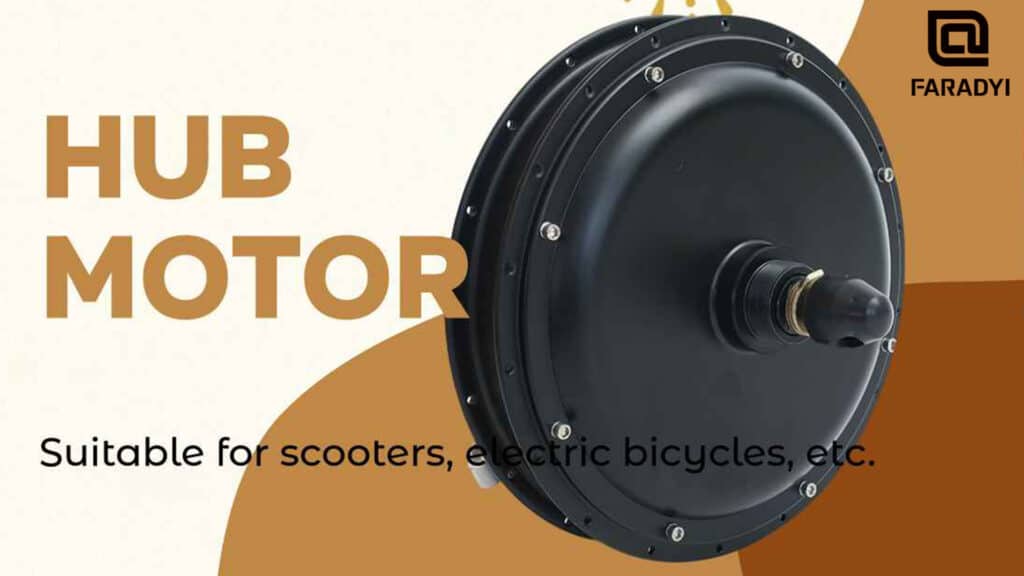
Introduction
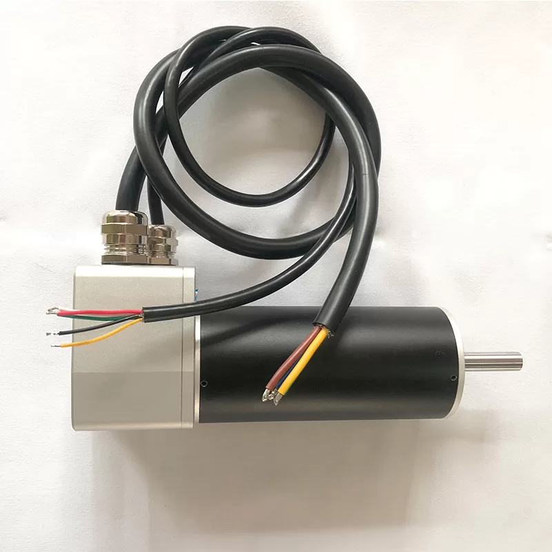
Brushless motor systems require position and current sensors for control. At least two-phase currents are necessary for controlling a three-phase brushless motor. Current sensing can be achieved by detecting the phase currents from the direct current bus, making one sensor sufficient for current control in brushless motors. However, if isolation is needed, the cost of current sensors tends to be higher. Alternatively, if isolation is not necessary, current can be obtained by measuring the voltage drop across precision resistors, resulting in lower costs. This latter method is widely used in low-cost brushless motor drivers.
Current Sensing Methods
In low-cost systems, the resistor sensors share common ground with the brushless driver processor, minimizing additional hardware. In such systems, it’s crucial to isolate the gate signals obtained from the brushless driver processor, especially when the system operates at voltages higher than 12V, like automotive voltages. Hall effect current sensors are ideal for current sensing isolation in brushless motor control.
Alternative Methods
Another method involves using MOSFET devices with built-in current sensors to detect current. However, estimating current using voltage drop across the MOSFET due to temperature effects can be inaccurate. For precise current control, this method is not feasible.
Importance of Current Feedback
High-performance brushless motor control is nearly impossible without current feedback. If precise torque and speed control are not required, both current feedback control and current sensors can be omitted, and a simple open-loop PWM voltage brushless driver based on duty cycle would suffice.
Challenges without Current Feedback
However, without current feedback, methods relying solely on duty cycle control without considering current control have drawbacks, especially in responding to changes in load torque. As load torque changes, rotor speed decreases, inducing a drop in induced electromotive force and thus an increase in stator phase current. This can be acceptable when only torque is controlled, proportional to the voltage duty cycle.
Conclusion
In conclusion, whether employing feedback or non-feedback current control, it’s essential to consider some form of current control due to the relatively small thermal time constants of inverter devices compared to brushless motors. Implementing methods such as current limiting control enhances system robustness.
Closing Thoughts
In applications where speed control is required, the voltage duty cycle must not be solely determined based on speed-adjusted portions. External speed feedback control is necessary for speed feedback closed-loop control, making speed sensing or detection crucial. A sensorless control system combined with current limiting control offers robustness and reliability.