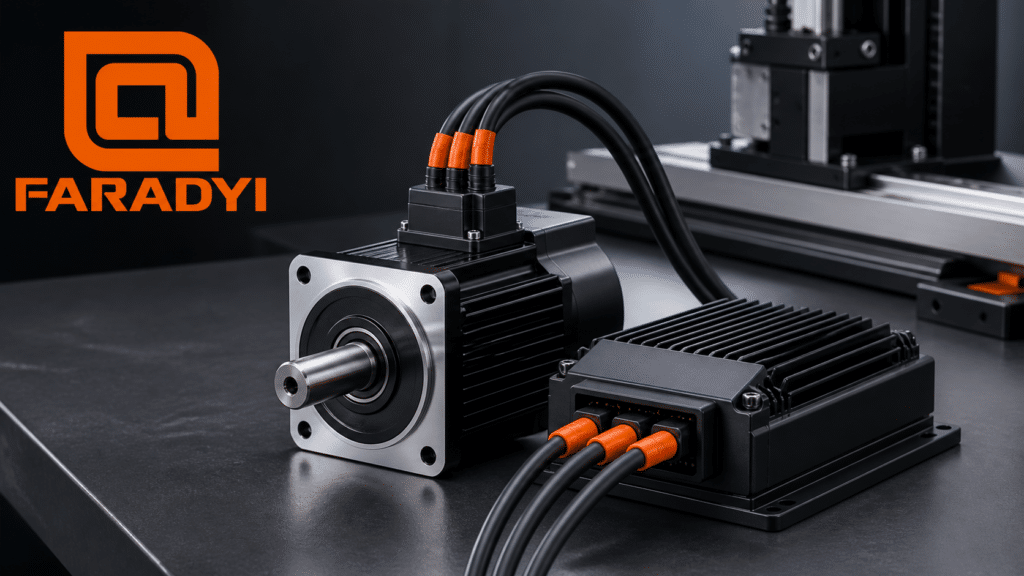
Designing permanent magnet brushless DC motors (BLDC motors) requires precise electromagnetic, thermal, and structural analysis. Today, engineers rely heavily on CAD software for brushless DC motors to accelerate development, improve accuracy, and optimize performance. Popular BLDC design tools include ANSYS, ANSOFT, MotorSolve, SPEED, Und Motor‑CAD, along with several emerging solutions developed in China.
This article explains the major CAD tools used for BLDC motor design, their workflows, and how engineers apply them to create high‑performance brushless motors for global industries.
Major CAD Software for BLDC Motor Design
MotorSolve (Infolytica, Canada)
MotorSolve BLDC is a specialized CAD platform introduced in 2006 for permanent magnet brushless DC motor design. It integrates classical analytical methods with finite element analysis (FEA) using the MagNet engine.
Hauptmerkmale
Automatic model and winding generation
Rotor/stator geometry editing
Pole/slot configuration
Material selection
Electromagnetic FEA simulation
Performance Outputs
Flux
Aktuell
Back‑EMF
Drehmoment
Iron losses
Copper losses
Effizienz
Cogging torque
MotorSolve also auto‑generates winding distributions based on inputs such as pole number, slot number, winding pitch, and phase offset. It calculates back‑EMF, winding factors, and harmonic content, making it ideal for BLDC optimization.
SPEED / PC‑BDC (University of Glasgow, UK)
SPEED is a widely used magnetic field design and analysis suite. Its PC‑BDC module focuses specifically on permanent magnet BLDC motor design.
Key Capabilities
Multi‑level electromagnetic analysis
Material database for magnets and laminations
Rotor/stator geometry templates
Iterative optimization tools
Torque, speed, and loss calculations
Typical SPEED Workflow
Review design requirements
Select rotor magnet and stator lamination materials
Choose rotor pole number and stator slot number
Input initial structural dimensions
Build electromagnetic model
Adjust geometry to meet torque/speed/loss targets
Select winding mode and optimize turns, wire diameter, and slot fill factor
Modify parameters (windings, air gap, magnet thickness)
Validate electromagnetic, thermal, and electrical performance
This iterative workflow helps engineers refine BLDC motor designs with high precision.
Motor‑CAD
Motor‑CAD provides combined electromagnetic + thermal simulation, allowing engineers to evaluate temperature rise, cooling strategies, and long‑term reliability.
Use Cases
Air‑gap optimization
Magnet thickness adjustments
Winding configuration changes
Thermal impact analysis
Motor‑CAD is often used alongside SPEED for complete BLDC motor evaluation.
China‑Developed BLDC CAD Tools
China has recently introduced several domestic BLDC motor design software solutions. These tools focus on:
Permanent magnet motor design
Electromagnetic simulation
Manufacturing‑ready optimization
They are increasingly adopted by motor manufacturers in Shenzhen, Guangzhou, Shanghai, and Suzhou.
BLDC Motor Design Workflow Using CAD Software
A typical BLDC motor design process includes:
1. Define Requirements
Torque, speed, losses, efficiency, and application constraints.
2. Select Materials
Permanent magnet grade + stator lamination steel (SPEED provides a full database).
3. Choose Rotor/Slot Geometry
Pole number, slot number, and initial dimensions.
4. Build Electromagnetic Model
Adjust geometry until torque, speed, and loss targets are met.
5. Optimize Windings
Turns, wire diameter, slot fill factor, and winding pitch.
6. Validate the Design
Check electromagnetic, thermal, and electrical performance.
7. Iterate Parameters
Modify windings, air gap, magnet thickness, etc., and observe impact on:
Drehmoment
Geschwindigkeit
Losses
Temperatur
Voltage/current behavior
8. Final Verification
Ensure the design meets all performance requirements.
Why Designer Expertise Still Matters
Even with advanced CAD tools, BLDC motor design still requires:
Strong theoretical knowledge
Correct parameter judgment
Understanding of electromagnetic trade‑offs
CAD software accelerates computation, but the designer’s experience determines the quality of the final motor.
Electromagnetic & Thermal Analysis Tools
BLDC motor electromagnetic and thermal calculations are typically performed using:
SPEED
Motor‑CAD
These tools help engineers evaluate:
Torque ripple
Loss distribution
Temperature rise
Voltage/current characteristics
FAQ: CAD Software for Brushless DC Motors
What CAD software is commonly used for BLDC motor design?
ANSYS, ANSOFT, MotorSolve, SPEED, Motor‑CAD, and several China‑developed tools.
How does MotorSolve help design BLDC motors?
It auto‑generates models and windings, performs FEA via MagNet, and outputs torque, losses, efficiency, and back‑EMF.
What is SPEED PC‑BDC?
A BLDC design module offering multi‑level electromagnetic analysis and iterative optimization.
Why is designer expertise still important?
Initial parameter selection and trade‑off decisions require human judgment.
Abschluss
CAD software for brushless DC motors plays a critical role in modern BLDC motor design. Tools like MotorSolve, SPEED, and Motor‑CAD help engineers accelerate development, improve accuracy, and optimize performance. Combined with expert knowledge, these tools enable high‑quality BLDC motor design for global industries.