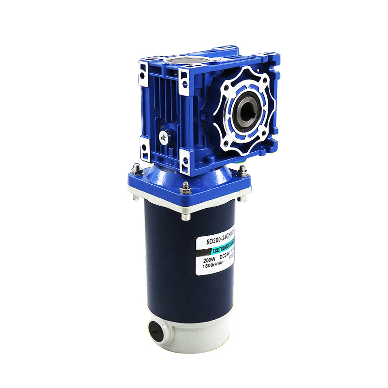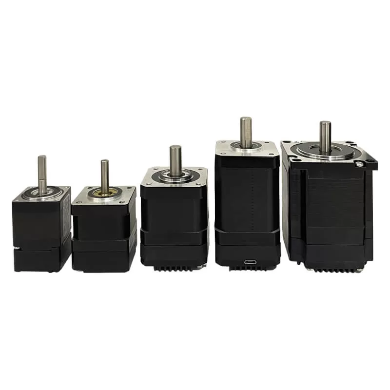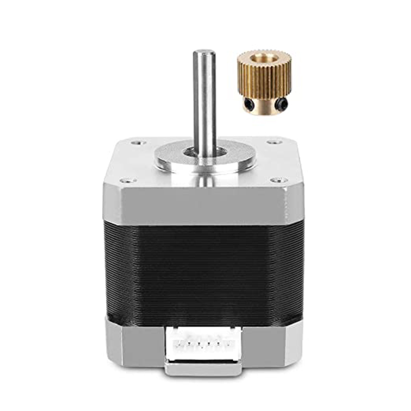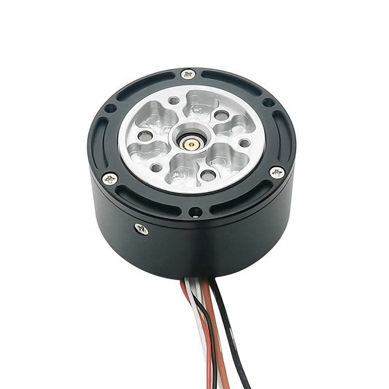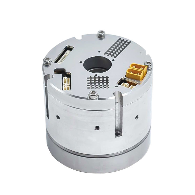
Brushless DC gear motors combine an electronically commutated BLDC motor with a reduction gearbox to provide lower output speed and higher load-side torque. The controller determines how the motor phases are energized, while sensors and control loops can regulate speed, torque, direction, or position. The best control method depends on startup load, low-speed smoothness, positioning accuracy, noise, efficiency, safety, and cost—not on the gearbox ratio alone.
Quick answer: Use six-step commutation for simple, cost-sensitive speed control; sinusoidal commutation when lower torque ripple and acoustic noise are important; and field-oriented control (FOC) when the application needs efficient, smooth, and precise torque or speed control. Choose sensored control for dependable startup, very low speed, or positioning. Sensorless control can reduce wiring and cost, but its low-speed and startup performance depends heavily on the algorithm and load.
Important distinction: Commutation and control mode are related but different. Six-step, sinusoidal, and FOC describe how the controller applies current to the motor phases. Speed, torque/current, and position control describe the variable the system is trying to regulate.
How Brushless DC Gear Motors Are Controlled
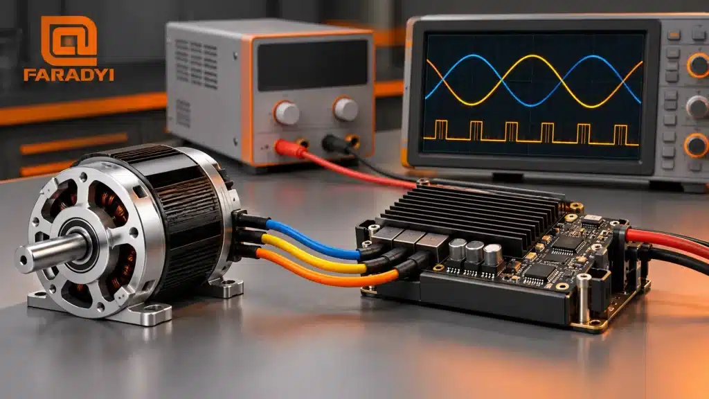
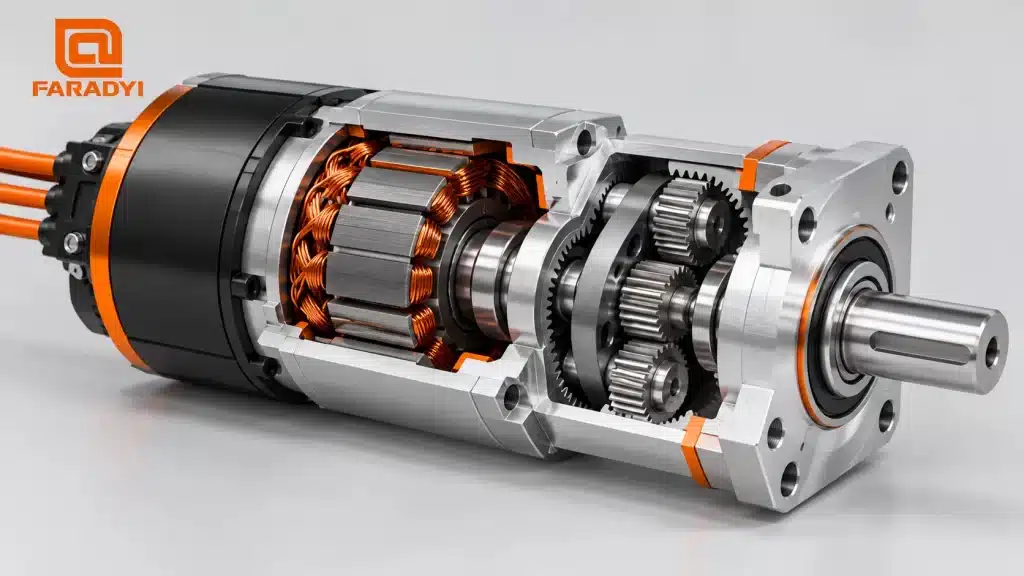
A complete gearmotor drive normally includes a DC supply, three-phase inverter or motor driver, control processor, BLDC motor, gearbox, and—when required—Hall sensors, an encoder, or another position-feedback device. The inverter electronically commutates the stator phases. The gearbox then reduces motor speed and multiplies output torque after its mechanical losses.
Power stage and electronic commutation
A BLDC controller switches semiconductor devices in a three-phase bridge to establish the rotating stator field. Pulse-width modulation (PWM) adjusts the effective phase voltage so the controller can regulate current or speed. Applying a fixed DC voltage directly to the motor phases cannot provide normal continuous rotation because a BLDC motor requires timed commutation.
Feedback and control loops
A current loop is usually the fastest loop and limits or regulates motor torque. A speed loop commands the current required to reduce speed error. A position loop, when used, commands the speed or torque needed to reach a target. Cascaded loops help keep the system stable and allow current limits to protect the motor, controller, gearbox, and load.
What the gearbox changes
The gearbox changes the relationship between motor motion and load motion. Output speed is approximately motor speed divided by ratio. Output torque is approximately motor torque multiplied by ratio and gearbox efficiency. Gear ratio also affects reflected inertia, acceleration, backlash, compliance, and the maximum permissible radial, axial, and shock loads. These factors must be included in controller tuning and motor sizing.
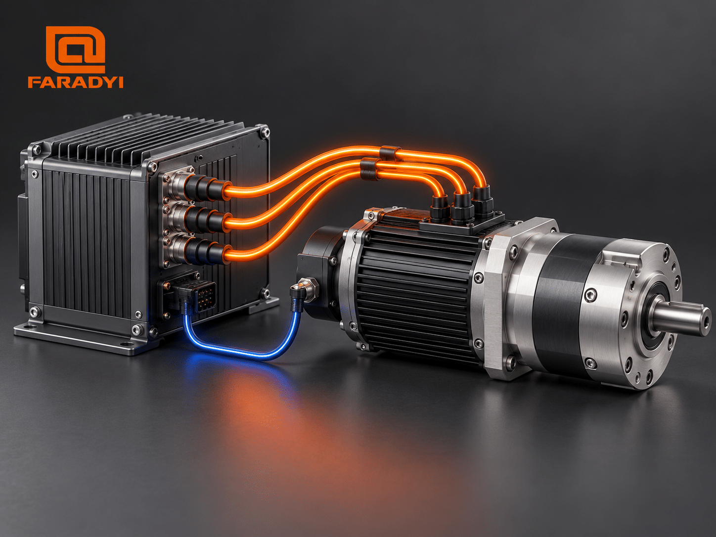 A closed-loop BLDC gearmotor system uses the controller to regulate phase current while encoder or Hall feedback reports rotor motion.
Speed, Torque, Position, and Direction Control
Speed control
In open-loop speed control, the controller applies a PWM command without directly correcting output-speed error. This can be adequate where load variation is small and exact speed is unnecessary. Closed-loop speed control compares measured speed with a command and adjusts torque-producing current to correct the difference. An encoder or Hall transitions can provide feedback, while some sensorless drives estimate speed from electrical signals.
Torque or current control
Within the motor’s normal unsaturated region, electromagnetic torque is approximately proportional to torque-producing current. Current control is therefore the practical basis of torque control. The command must remain within the motor’s continuous and peak current limits, the controller rating, the gearbox input and output torque limits, and the permitted duty cycle. Output torque should not be inferred from DC-bus current alone.
Position control
Position control requires feedback with enough resolution and repeatability for the application. A motor-side encoder measures rotor position and benefits from the gearbox ratio, but gearbox backlash and compliance still affect load position. A load-side encoder measures the actual output and can compensate for some drivetrain error, although it requires a more carefully designed control loop.
Forward, reverse, braking, and holding
Direction is reversed by changing the electronic commutation sequence or torque command—not by casually swapping the DC supply polarity. During deceleration, the motor may return energy to the DC bus. The controller and power supply must be designed for regenerative energy or provide an appropriate braking path. A motor producing zero-speed holding torque continues to create heat; safety-critical or power-off holding applications may need a mechanical brake.
BLDC Commutation Methods Compared
Each commutation method can be combined with different command interfaces and control loops. The following table is a practical comparison rather than a universal ranking.
On a phone, swipe horizontally to view the complete table.
| Method | How it works | Strengths | Limitations | Typical fit |
|---|---|---|---|---|
| Six-step / trapezoidal | Sequentially energizes phase pairs in six electrical sectors. | Simple, economical, robust, lower processing demand | More torque ripple and audible noise; less refined low-speed motion | Pumps, fans, conveyors, simple actuators |
| Sinuskommutierung | Applies smoothly varying phase currents based on rotor position. | Lower torque ripple, quieter operation, smoother motion | More computation and position information than basic six-step control | Quiet mechanisms, instruments, precision equipment |
| Field-oriented control (FOC) | Transforms measured currents into rotor-aligned components and controls flux- and torque-producing current separately. | Smooth torque, strong efficiency potential, precise dynamic control, low acoustic noise | Requires accurate current measurement, motor parameters, rotor-angle information or estimation, and careful tuning | Robotics, servo axes, medical equipment, automated machinery |
Sensored vs. Sensorless Control
Rotor-position information may come from Hall sensors, an incremental or absolute encoder, a resolver, or a sensorless estimator. The right choice depends on the lowest operating speed, starting load, motion accuracy, environment, and wiring constraints.
On a phone, swipe horizontally to view the complete table.
| Approach | Vorteile | Tradeoffs | Choose it when |
|---|---|---|---|
| Hall sensors | Reliable sector information from standstill, simple integration | Limited angular resolution; additional wires and components | Loaded startup and basic closed-loop speed control are required. |
| Encoder or resolver | Higher resolution, precise low-speed and position control | Higher cost, wiring, alignment, and environmental considerations | Positioning, smooth near-zero speed, or accurate servo response matters. |
| Sensorless estimation | Fewer motor wires and sensors; potential cost and packaging benefits | Back-EMF methods weaken at zero and very low speed; startup under load may be challenging | The load permits the selected startup method and most operation occurs above the estimator’s reliable speed range. |
How the Gearbox Affects Control Performance
- Ratio: A higher ratio increases nominal output torque and encoder counts per output revolution, but reduces output speed.
- Effizienz: Friction means actual output torque is lower than the ideal motor-torque × ratio calculation. Efficiency can vary with load, speed, direction, temperature, and gearbox type.
- Backlash: Lost motion can cause position error, reversal delay, noise, or control-loop oscillation. Low-backlash gearing or load-side feedback may be needed.
- Reflected inertia: A reduction ratio changes the load inertia seen by the motor, which affects acceleration and controller tuning.
- Mechanical ratings: Continuous torque, peak torque, emergency-stop loads, radial load, axial load, and output-bearing life must all be checked.
- Self-locking assumptions: Do not assume a gearbox will hold a suspended or safety-critical load when power is removed. Verify backdrivability and use a rated brake or other safety device when required.
How to Choose a Control Method
- Define the load cycle. Record output speed, continuous torque, peak torque, peak duration, acceleration, reversals, and dwell time.
- Define motion quality. Specify speed regulation, positioning accuracy, repeatability, allowable backlash, torque ripple, and acoustic noise.
- Check startup and minimum speed. A high starting load or near-zero-speed operation often favors sensored control.
- Select gearbox ratio and type. Verify rated and emergency loads, efficiency, life, backlash, radial and axial loads, and lubrication orientation.
- Match motor and controller. Check bus voltage, continuous and peak phase current, motor winding, maximum speed, feedback interface, switching frequency, and protective functions.
- Plan braking energy. Confirm whether the supply can absorb regenerative energy or whether a brake resistor, clamp, or other solution is required.
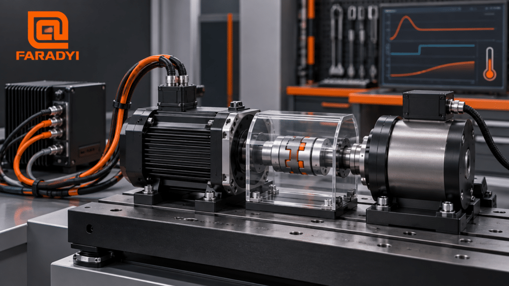
- Validate the complete system. Test output torque, speed, temperature, stability, noise, stopping, and fault behavior under the real duty cycle.
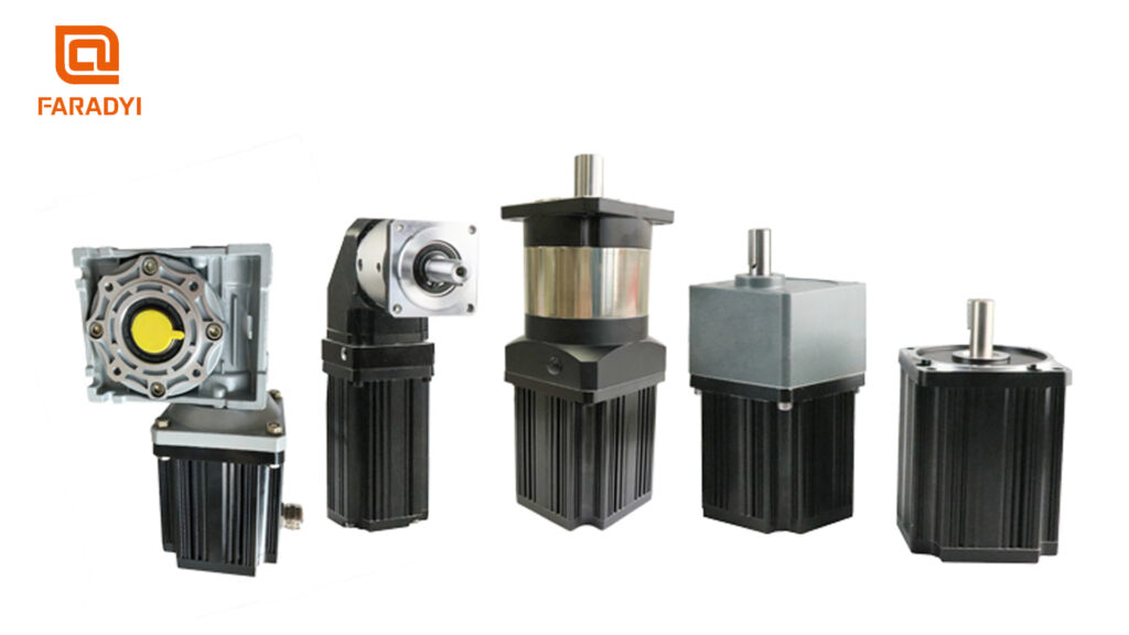
Faradyi’s brushless DC motor range includes multiple form factors and application options that can be reviewed as a starting point. A final gearmotor and controller selection should be confirmed against model-specific motor curves, gearbox ratings, feedback requirements, and the actual duty cycle.
Common Control Problems and What to Check
The motor starts poorly or runs backward
Verify phase order, Hall sequence, encoder direction, electrical-angle alignment, and the controller’s motor-identification procedure. Do not change wiring while the system is energized.
Speed changes too much with load
Check whether the system is operating open loop, hitting a current limit, reaching its voltage limit at speed, or experiencing excessive mechanical friction. Closed-loop speed control can improve regulation only when sufficient torque and voltage headroom remain.
The output oscillates or chatters
Review control-loop gains, feedback noise, encoder resolution, backlash, compliance, load inertia, and coupling stiffness. Aggressive tuning cannot remove mechanical backlash and may make the response worse.
The motor, controller, or gearbox overheats
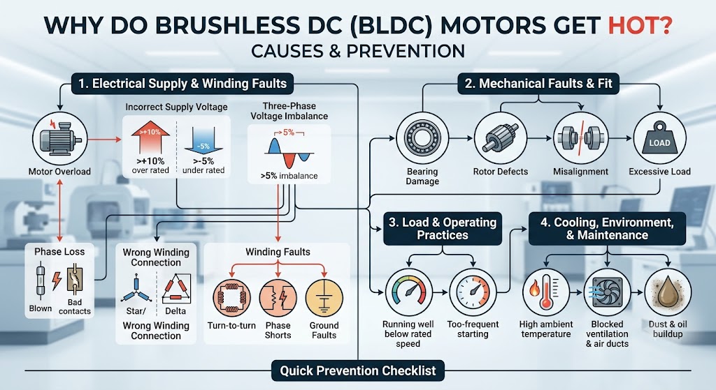
Measure motor phase current, motor winding or housing temperature, controller temperature, gearbox temperature, loaded speed, and duty cycle together. Check for poor commutation, excessive current, undersized gearing, frequent reversals, mechanical binding, inadequate cooling, or operation beyond the continuous rating.
Applications for Brushless DC Gear Motors
Brushless DC gear motors are used where compact electronically controlled motion must be converted into practical load torque. Common examples include conveyors, automated doors, valve actuators, mobile robots, service robots, packaging equipment, medical mechanisms, pan-and-tilt systems, pumps, and industrial positioning axes.
The application determines the appropriate solution. A conveyor may prioritize reliable speed regulation and overload protection. A robotic joint may require FOC, high-resolution feedback, low backlash, and carefully managed reflected inertia. A battery-powered actuator may place more emphasis on efficiency, standby current, regenerative behavior, and compact packaging.
Information to Provide for a Gearmotor Quotation
- DC bus or supply voltage and available current
- Required output speed range and speed-regulation tolerance
- Continuous output torque, peak torque, peak duration, and duty cycle
- Acceleration, reversals, stopping time, and load inertia
- Desired gear ratio, gearbox type, backlash, and backdrivability
- Radial, axial, shock, and suspended-load conditions
- Speed, torque, or position-control objective and command interface
- Hall sensors, encoder, brake, or load-side feedback requirements
- Dimensions, mounting, shaft, connector, cable, and mass limits
- Ambient temperature, ingress protection, noise, life, and expected quantity
Need a BLDC gearmotor matched to your control requirements?
Share your voltage, output speed, continuous and peak torque, duty cycle, gear ratio, backlash, feedback, controller interface, dimensions, and operating environment with Faradyi Motor. These details help the engineering team review the complete operating point.
Häufig gestellte Fragen
Can the speed of a brushless DC gear motor be controlled with voltage?
The controller may use PWM to vary effective phase voltage, but a BLDC motor also requires electronic commutation. Closed-loop systems regulate speed by comparing feedback with a command and adjusting torque-producing current. Supply voltage must still provide enough headroom at the required motor speed.
What is the best control method for brushless DC gear motors?
There is no universal best method. Six-step control is often suitable for simple cost-sensitive motion. Sinusoidal commutation can reduce noise and torque ripple. FOC is a strong choice for smooth, efficient, and precise dynamic control, provided the controller, sensing, tuning, and budget support it.
Can a sensorless BLDC gear motor start under load?
Some sensorless controllers can start under load using alignment, open-loop startup, high-frequency injection, or other estimation methods, but capability varies significantly. Traditional back-EMF detection is weak at zero speed. Confirm startup torque and load conditions with the specific controller.
Does a gearbox improve position accuracy?
A reduction ratio increases motor-side encoder counts per output revolution, which can improve commanded resolution. However, backlash, elastic deformation, wear, and manufacturing error can limit actual load accuracy. Low-backlash gearing or load-side feedback may be necessary.
How is a brushless DC gear motor reversed?
The controller reverses the commanded torque or commutation sequence. The system must also handle deceleration energy, gearbox backlash, load inertia, and any directional mechanical limits. Do not reverse the DC supply polarity unless the controller documentation specifically permits it.
Should the encoder be mounted on the motor or gearbox output?
A motor-side encoder supports commutation and high-bandwidth control, while a load-side encoder measures the actual output after backlash and compliance. Some precision systems use both. The best arrangement depends on accuracy, dynamic response, safety, packaging, and controller capability.
Abschluss
Effective control of brushless DC gear motors requires the motor, controller, feedback, gearbox, power supply, and load to be treated as one system. Choose the commutation method according to smoothness, efficiency, dynamic response, and cost. Choose the feedback and control loops according to startup, minimum speed, torque, and positioning requirements. Finally, verify current, thermal, regenerative, and mechanical limits across the complete duty cycle before releasing the design.
Technical References
- Microchip Technology, AN885: Brushless DC (BLDC) Motor Fundamentals — BLDC construction, characteristics, commutation, and control fundamentals.
- Texas Instruments, Three-Phase BLDC and PMSM Motor Control Reference Design — sensored and sensorless trapezoidal control and field-oriented control.
- Microchip Developer Help, Introduction to BLDC Motor Commutation and Control Architectures — sensored, sensorless, power-stage, and modulation concepts.