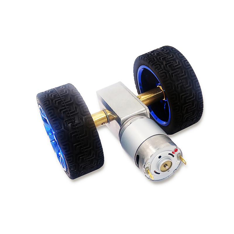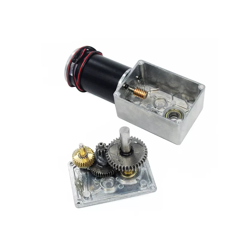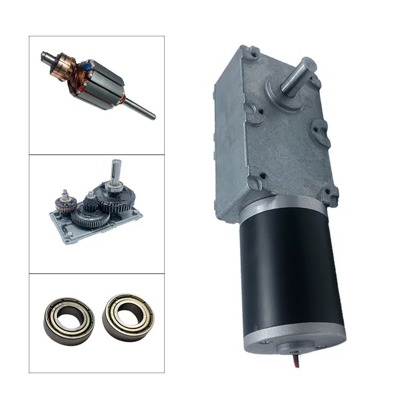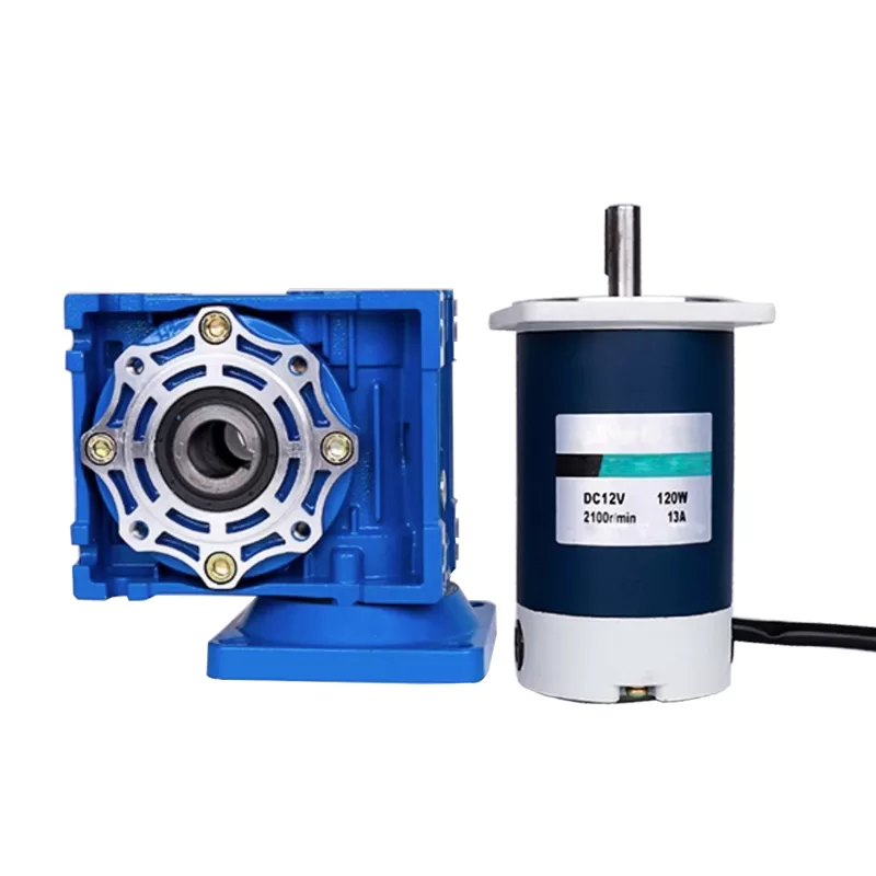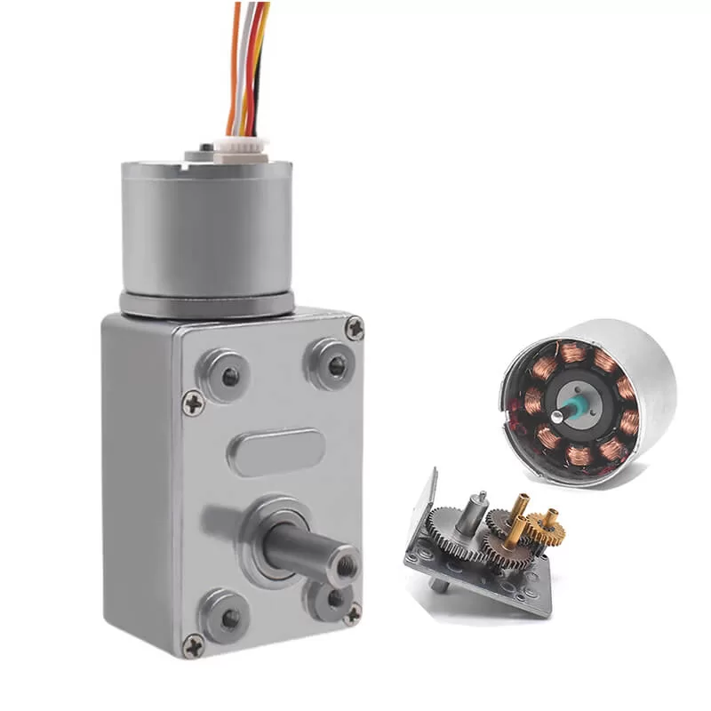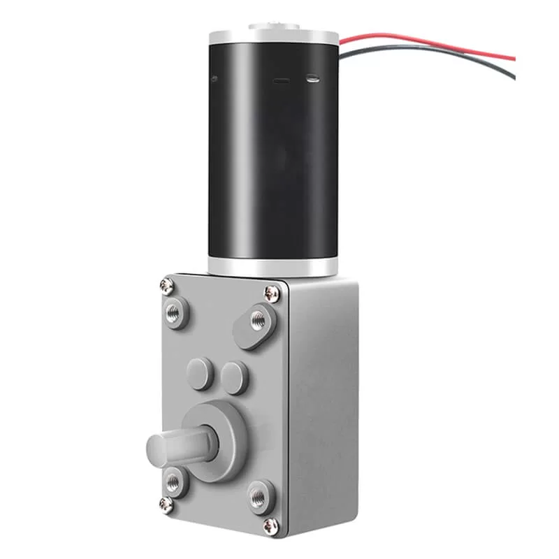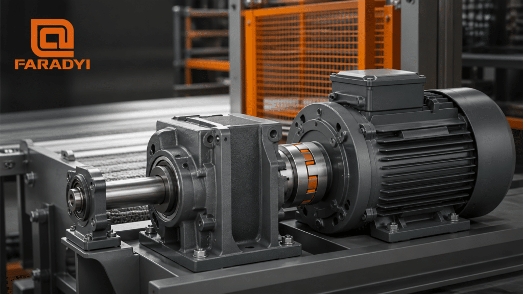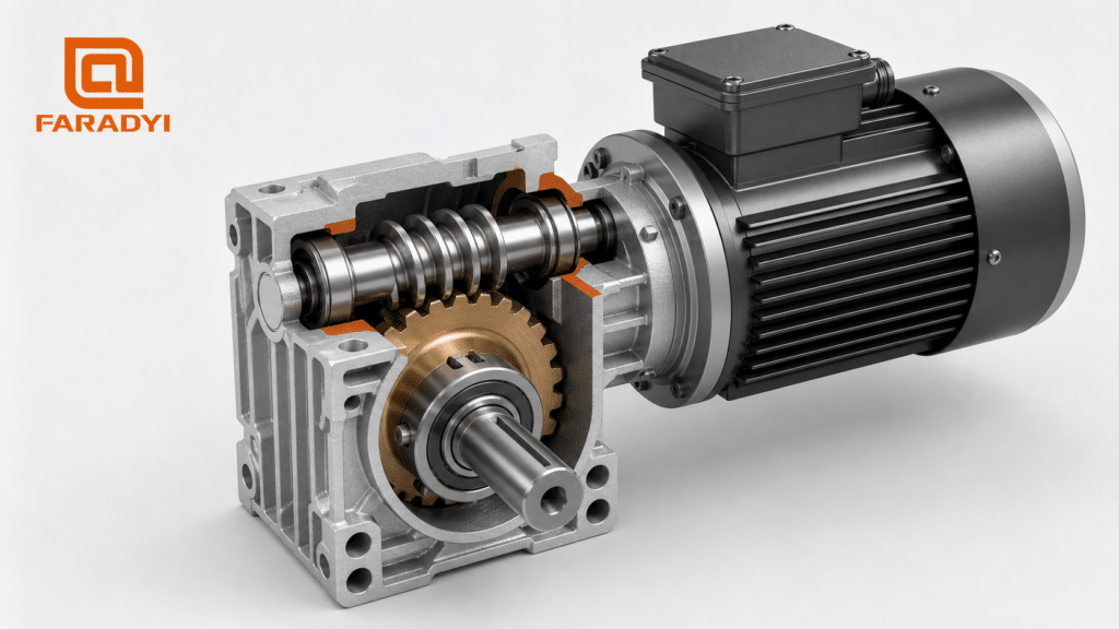
A worm drive electric motor combines an electric motor with a right-angle worm gearbox to reduce output speed and increase output torque in a compact package. The motor turns a screw-shaped worm, which meshes with a worm wheel mounted on the output shaft. This arrangement can deliver a large reduction ratio in one gear stage and may resist back-driving when its geometry and friction conditions permit.
Worm drive motors are used in conveyors, gates, valves, lifting mechanisms, positioning systems, packaging equipment, and other machines that need slow, high-torque output or a 90-degree change in the direction of power transmission.
They also involve important tradeoffs. Sliding contact between the worm and wheel generates friction and heat, so a worm gearbox is not always the most efficient choice. Self-locking is also not guaranteed for every worm drive and should not be treated as a safety brake without application-specific validation.
What Is a Worm Drive Electric Motor?

A worm drive electric motor—also called a worm gear motor or worm geared motor—is an integrated drive consisting of an electric motor and a worm gear reducer.
The motor supplies high-speed rotary motion to the worm shaft. The threaded worm meshes with the teeth of the worm wheel, which normally turns an output shaft positioned at approximately 90 degrees to the motor shaft.
Because the worm can engage a wheel with many teeth, the gearbox can achieve a relatively high speed reduction in a single stage. As the output speed decreases, the available output torque increases, minus the power lost through gear-mesh friction, bearings, seals, and lubrication.
Worm drive motors can be built with brushed DC, brushless DC, AC induction, stepper, or servo motors. The best motor type depends on the power supply, required control, duty cycle, maintenance target, and operating environment.
How Does a Worm Drive Electric Motor Work?
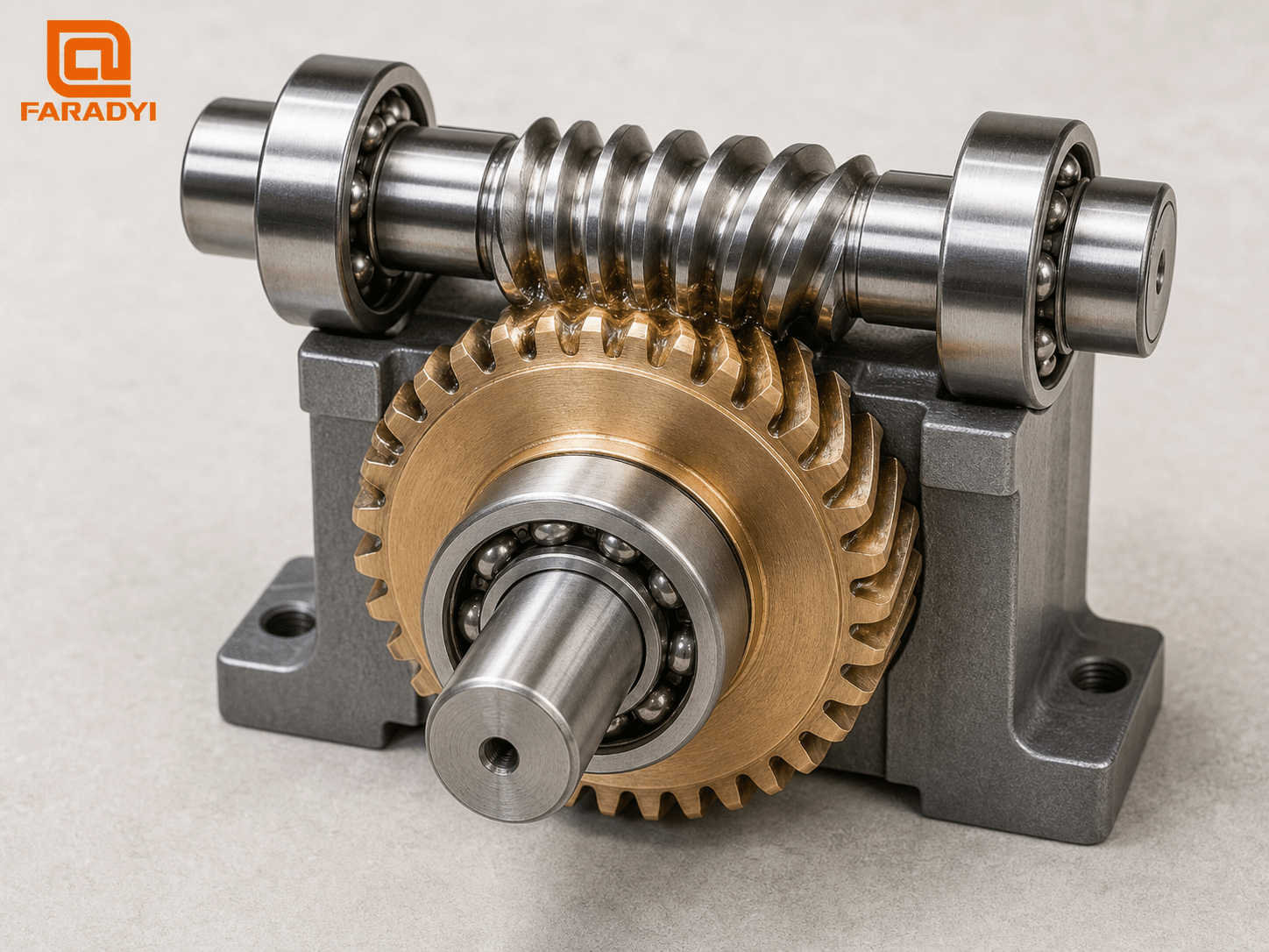
The operating sequence is straightforward:
- The electric motor turns the input shaft.
- The input shaft rotates the screw-shaped worm.
- The worm’s helical thread pushes against the teeth of the worm wheel.
- The worm wheel rotates more slowly on a perpendicular output shaft.
- The reduction converts high motor speed into lower output speed and greater output torque.
For a simplified worm set, the reduction ratio is calculated by dividing the number of teeth on the worm wheel by the number of starts on the worm.
For example, a 30-tooth worm wheel driven by a single-start worm has a nominal 30:1 ratio. If the worm has two starts, the same wheel produces a nominal 15:1 ratio.
A higher numerical ratio normally gives lower output speed and greater torque multiplication, but it does not create energy. Actual output torque must account for gearbox efficiency and the motor’s real operating point.
Main Components of a Worm Gear Motor
Electric Motor
The motor supplies the input power. Brushed DC motors offer simple speed and direction control. Brushless DC motors provide longer service life and lower maintenance but need electronic commutation. AC motors are common in fixed industrial equipment, while stepper and servo motors support positioning applications.
Worm Shaft
The worm is a screw-shaped gear connected to or machined into the input shaft. Its number of starts, lead angle, material, surface finish, and heat treatment influence ratio, efficiency, wear, and back-drivability.
Worm Wheel
The worm wheel meshes with the worm and transfers motion to the output shaft. A hardened steel worm paired with a bronze wheel is a common industrial combination because it offers strength and favorable wear behavior. Engineering plastics may be used in lighter-duty applications where low noise, weight, or cost is important.
Housing and Bearings
The housing supports and aligns the shafts, bearings, seals, and gear mesh. Aluminum housings reduce weight and dissipate heat well, while cast iron can provide rigidity and vibration damping. Bearings must support the radial and axial forces produced by the gearset.
Lubrication
Worm drives depend on suitable oil or grease to reduce sliding friction, wear, and heat. The lubricant must match the materials, speed, load, temperature, orientation, and maintenance interval.
Worm Drive Electric Motor Advantages
High Reduction Ratio in One Stage
A worm stage can provide substantial speed reduction without requiring several pairs of external gears. This can simplify a drive that needs slow output motion.
Compact Right-Angle Layout
The input and output shafts are normally perpendicular. This makes a worm gearmotor useful when the driven shaft must turn 90 degrees or when the machine has limited inline space.
High Output Torque at Low Speed
Speed reduction multiplies torque at the output. The usable result depends on motor torque, ratio, efficiency, thermal limits, service factor, and duty cycle.
Smooth and Quiet Operation
Worm gearing uses sliding contact with gradual tooth engagement. A correctly designed, aligned, and lubricated unit can operate smoothly and quietly compared with some other gear configurations.
Potential Resistance to Back-Driving
Some worm gearsets resist rotation from the output side. This may help a mechanism hold position after power is removed. However, self-locking is a system behavior—not an automatic feature of every worm motor.
Limitations and Engineering Tradeoffs
Lower Mechanical Efficiency
The worm and wheel slide against one another as they transmit power. This produces more friction than the predominantly rolling contact found in many spur, helical, or planetary gearsets.
Efficiency varies with lead angle, ratio, materials, lubrication, temperature, input speed, load, manufacturing quality, and whether the gearbox is fully run in. Use the manufacturer’s efficiency data at the intended operating point rather than relying on a universal percentage.
Heat Generation
Mechanical power lost through friction becomes heat. Continuous-duty applications may require a larger gearbox, a thermally conductive mounting surface, better ventilation, a different lubricant, or another gearbox architecture.
Backlash
Clearance is needed to allow lubrication and prevent binding, but it produces rotational play when direction reverses. Backlash can affect positioning accuracy and repeatability. A precision or adjustable-backlash worm reducer may help, but it can increase cost and maintenance sensitivity.
Wear and Lubrication Requirements
Incorrect lubrication, contamination, misalignment, overload, or excessive temperature can accelerate wear. Maintenance requirements should be considered during gearbox selection—not after installation.
Limited Back-Drivability
Resistance to back-driving is useful in some holding applications but undesirable when the load needs to move the motor, absorb external impacts, or be repositioned manually.
Are Worm Gear Motors Self-Locking?
Some worm gear motors can be self-locking, but not all of them are. Self-locking depends on the relationship between the worm’s lead angle and the effective friction in the gear mesh.
Factors that affect back-drivability include:
- Worm lead angle and number of starts
- Gear ratio and tooth geometry
- Worm and wheel materials
- Lubricant type and temperature
- Surface finish and wear condition
- External load, vibration, and shock
- Whether the unit is stationary or moving
A gearbox that appears locked while stationary may behave differently under vibration, after wear, or while decelerating. Static self-locking and dynamic stopping behavior are not identical.
Worm Drive Motor vs. Other Gearmotor Types
| Characteristic | Worm | Spur/helical | Planetary |
|---|---|---|---|
| Shaft arrangement | Typically right-angle | Typically parallel or inline | Coaxial |
| Ratio per stage | High | Low to moderate | Moderate |
| Typical efficiency | Lower and highly design-dependent | Generally high | Generally high |
| Back-drivability | May resist back-driving | Usually back-drivable | Usually back-drivable |
| Best-known strength | Compact right-angle reduction | Efficiency and simplicity | High torque density and coaxial output |
| Common concern | Heat and sliding wear | Multiple stages needed for high ratios | Cost and design complexity |
General comparison only. Actual performance depends on the gearbox design, ratio, load, materials, lubrication, and operating conditions. On a phone, swipe horizontally to view the complete table.
Common Worm Drive Electric Motor Applications
Conveyors and Material Handling
Worm gearmotors can provide slow, controlled output and a compact right-angle package for small conveyors, indexing mechanisms, and material-handling equipment.
Gates, Doors, and Window Actuators
The compact layout and possible resistance to back-driving are useful in opening and closing mechanisms. Safety systems must still use appropriate limit switches, obstruction detection, brakes, and mechanical protection.
Valves and Dampers
Worm reducers can create high output torque for rotating valves and airflow dampers. Position feedback and limit controls may be added when the mechanism must stop accurately.
Packaging and Food-Processing Equipment
Right-angle gearmotors fit compact machine layouts and can drive feeders, guides, conveyors, and adjustment mechanisms. Washdown or food-contact environments require suitable enclosures, seals, finishes, and lubricant choices.
Solar Trackers and Positioning Systems
High reduction and low output speed can support controlled angular positioning. Designers must account for wind loading, backlash, outdoor sealing, fatigue, and a safe holding method.
Robotics and Automation
Worm drives can be useful for low-speed joints, grippers, fixtures, and adjustment axes that benefit from a right-angle package or resistance to back-driving. Applications needing very low backlash, high efficiency, or easy back-driving may be better served by planetary, harmonic, cycloidal, or direct-drive solutions.
How to Select a Worm Drive Electric Motor
Start with the load and motion profile rather than selecting by motor wattage alone.
- Define output speed. Specify the required loaded output RPM, not only the motor’s no-load speed.
- Calculate continuous output torque. Include friction, gravity, process forces, acceleration, and realistic mechanical losses.
- Calculate peak torque. Account for startup, jams, shock loads, emergency stops, and their duration.
- Select the gear ratio. Match motor speed to output speed while checking the motor’s torque-speed curve and gearbox efficiency.
- Define duty cycle. Record run time, rest time, starts per hour, reversals, and expected service life.
- Check thermal limits. Evaluate ambient temperature, airflow, mounting, lubricant, enclosure, and heat from continuous operation.
- Decide whether back-driving is required. Verify self-locking with the supplier, or specify a brake when reliable holding is necessary.
- Set backlash and positioning requirements. Determine whether ordinary motion, repeatable indexing, or closed-loop precision is required.
- Choose the motor and control type. Compare brushed DC, BLDC, AC, stepper, and servo options.
- Confirm mechanical integration. Check shaft diameter, single or dual output, mounting orientation, radial and axial loads, housing size, and weight.
- Define the environment. Consider dust, moisture, washdown, corrosion, noise, vibration, and required IP protection.
- Prototype at the real operating point. Measure output speed, current, temperature rise, noise, backlash, stopping behavior, and life in the assembled machine.
Information to Provide for a Worm Gearmotor Recommendation
Send the following details to the motor supplier:
- Available AC or DC voltage and current
- Required loaded output speed
- Continuous and peak output torque
- Peak-torque duration and load profile
- Duty cycle and starts per hour
- Required gear ratio, if already known
- Back-driving or holding requirement
- Allowable backlash and positioning accuracy
- Shaft dimensions and mounting orientation
- Radial and axial output-shaft loads
- Ambient temperature and enclosure requirements
- Encoder, brake, limit switch, or controller requirements
- Expected annual quantity
Faradyi Motor offers configurable AC and DC worm gearmotor solutions, including shaft, mounting, ratio, enclosure, encoder, brake, and thermal-protection options. Explore the Faradyi worm drive electric motor range or send your application parameters to request an engineering recommendation and quotation.
Questions fréquemment posées
What is a worm drive electric motor?
It is an electric motor combined with a worm gearbox. The motor turns a screw-shaped worm that drives a perpendicular worm wheel, reducing speed and increasing output torque.
Why use a worm gear motor?
Choose one when the application needs a compact right-angle layout, a substantial single-stage reduction, slow high-torque output, smooth operation, or possible resistance to back-driving.
Can every worm gear motor self-lock?
No. Self-locking depends on lead angle, friction, materials, lubrication, load, temperature, vibration, wear, and motion state. Confirm performance with the manufacturer and use a rated brake for safety-critical holding.
Can a worm drive be back-driven?
Some worm drives can be back-driven, particularly designs optimized for higher efficiency or with larger lead angles. Back-drivability must be evaluated for the specific gearbox and operating conditions.
How do I calculate worm gear ratio?
For a basic worm set, divide the worm wheel’s number of teeth by the worm’s number of starts. A 40-tooth wheel driven by a two-start worm has a nominal 20:1 ratio.
Are worm gear motors efficient?
Efficiency varies widely. Sliding contact generally makes worm drives less efficient than comparable spur, helical, or planetary gearsets. Lead angle, ratio, load, speed, materials, lubrication, and temperature all affect the result.
Can a worm gear motor run continuously?
Yes, if the motor and gearbox are rated for the required continuous torque, speed, duty, lubrication, and thermal conditions. Validate temperature rise in the actual installation.
Can I reverse a worm drive motor?
Many worm drive motors can operate in both directions, provided the motor, gearbox, bearings, lubrication system, and driven load are rated for reversing service.
Conclusion
A worm drive electric motor combines an electric motor with a right-angle worm reducer to convert high input speed into slow, high-torque output. Its compact layout, large single-stage reduction, smooth operation, and possible resistance to back-driving make it valuable in conveyors, actuators, valves, gates, positioning systems, and industrial equipment.
The same sliding contact that enables smooth reduction also creates friction, heat, and efficiency losses. Self-locking should be verified rather than assumed, and safety-critical holding requires a properly engineered brake or locking system.
To identify a suitable configuration, compare output speed, continuous and peak torque, ratio, efficiency, duty cycle, temperature, backlash, back-driving behavior, shaft loads, controls, and environmental requirements. Review Faradyi worm drive electric motors and send the engineering team your application data for a customized recommendation.
Technical References