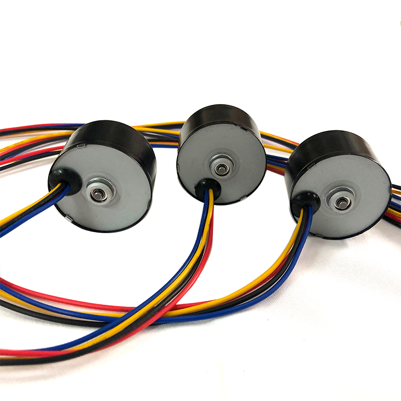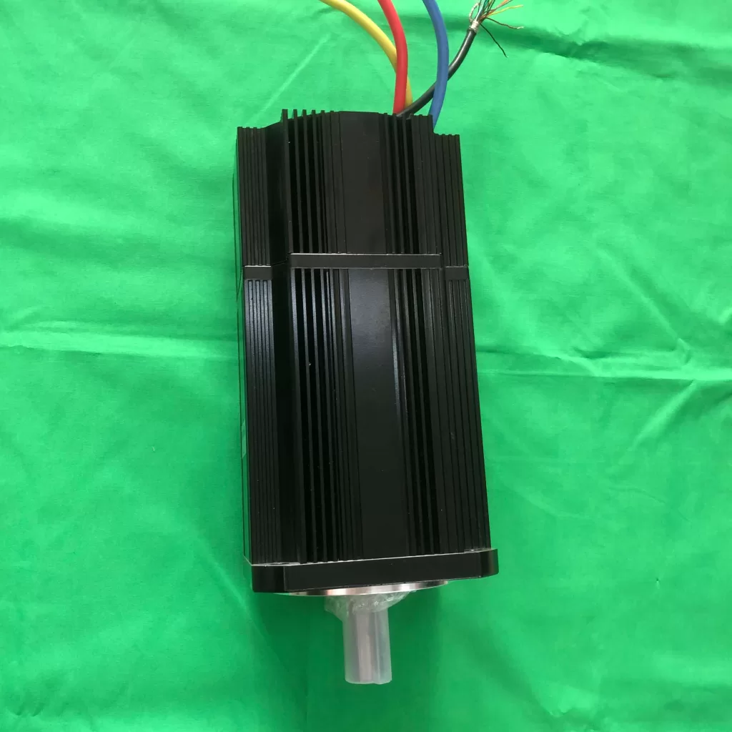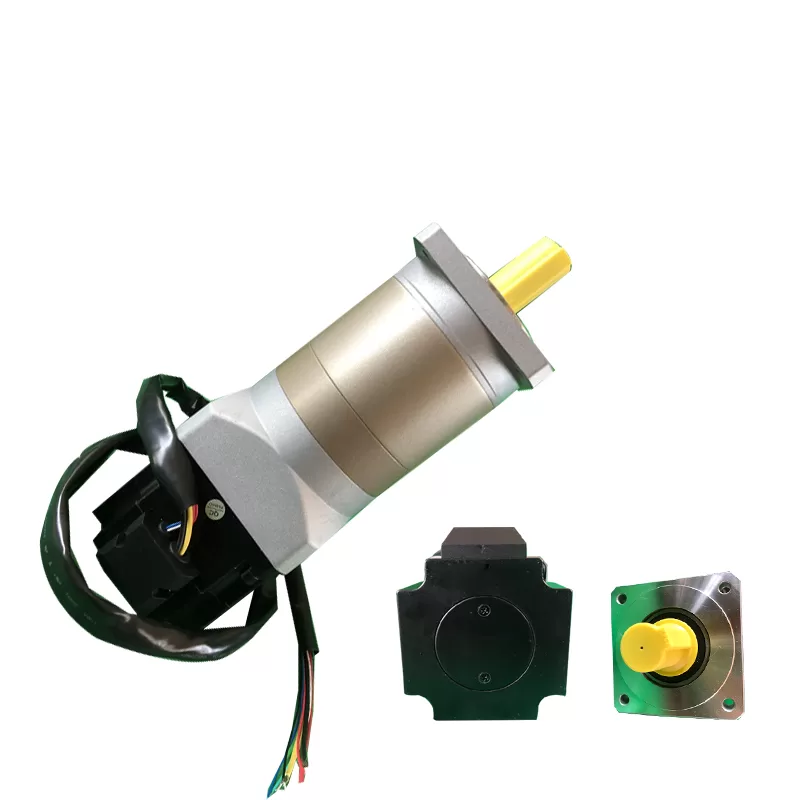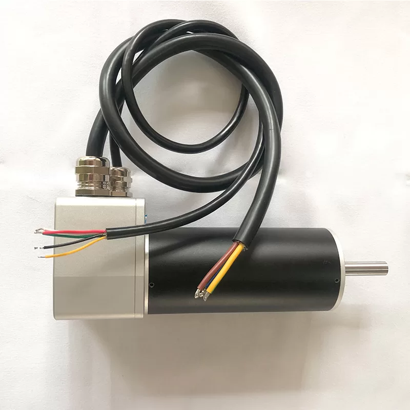
BLDC rotor position estimation tells a controller where the rotor’s magnetic field is so it can energize the windings at the right time. Some drives measure position with sensors. Others infer it from electrical measurements and a motor model. The right approach depends on how the machine starts, runs, reverses, and holds its load.
Electrical angle is not mechanical shaft position
Commutation uses the rotor’s electrical angle. A positioning machine may also need the shaft’s mechanical angle or the actual load position. These quantities are related, but they are not interchangeable.
One mechanical revolution contains as many electrical cycles as the motor has pole pairs. For example, a four-pole-pair motor completes four electrical cycles per shaft revolution. In an aligned system, electrical angle follows mechanical angle multiplied by pole pairs, with the appropriate offset and wrapping. Incorrect pole-pair or alignment settings can therefore disrupt commutation even when a sensor appears to be working.
Knowing commutation angle does not automatically establish absolute shaft position after power-up. Multi-turn position, homing, transmission backlash, and feedback at the load are separate requirements.
BLDC rotor position estimation and feedback options
On a phone, swipe horizontally to read the comparison.
| Approach | Information available | Main selection question |
|---|---|---|
| Digital Hall sensors | Coarse electrical sectors, including at standstill | Are sector-level feedback and the drive’s interpolation sufficient? |
| Encodeur | Measured angular increments or absolute angle, depending on type | What accuracy, interface, startup alignment, and installation are required? |
| Resolver | Analog position signals requiring excitation and conversion | Does the drive support the resolver and environmental requirements? |
| Back-EMF zero crossing | Timing information from a floating phase in suitable six-step control | How will the motor start and operate below the usable detection speed? |
| Model-based observer | Estimated electrical angle from measured electrical behavior | How sensitive is it to parameters, noise, load changes, and low speed? |
| Signal injection | Position-related response to deliberately applied excitation | Does this particular motor-drive combination provide usable saliency information? |
How back-EMF position detection works
As permanent magnets move past the stator windings, they generate back electromotive force. A conventional six-step drive can observe the undriven phase during suitable intervals and use its zero crossings to time commutation. Switching transients, current decay, and filtering complicate the measurement.
In an ideal six-step description, commutation follows a detected crossing after a delay corresponding to 30 electrical degrees. Practical timing may compensate for filtering, speed, and the selected control strategy. Do not treat a single delay or blanking time as correct for every motor.
Back-EMF becomes weaker as speed falls and is absent at standstill. That is why a drive that runs well at speed may hesitate during a loaded start or reversal. The controller needs an appropriate way to establish initial position and accelerate into the range where its estimator is reliable.
Why sensorless FOC uses a different approach
FOC needs a continuously updated electrical angle. A typical sensorless implementation uses electrical measurements and a model to estimate back-EMF or another internal state, then tracks angle with an observer or phase-locked loop. It does not simply apply a floating-phase zero-crossing rule while all phases are actively controlled.
Current measurement quality, voltage reconstruction, winding resistance, inductance, and computation delay affect the result. Resistance changes with temperature, and inverter behavior can differ from the ideal voltage command. A model-based estimate is only as useful as the assumptions and measurements supporting it.
See the FOC and vector-control guide for the wider control loop, and our BLDC current-sensing guide for the measurement side.
Startup, low speed, and reversals deserve their own tests
A common startup sequence aligns the rotor, applies a controlled acceleration pattern, and transfers to closed-loop estimation once the available signal is sufficient. The sequence must suit the load. A pump, an unloaded fan, and a gravity-loaded joint may need very different behavior.
Alignment can cause movement, and an open-loop ramp can lose synchronism if the load cannot follow. Also consider a rotor that is already spinning when power is applied. Windmilling detection, restart, and reversal behavior should be verified rather than assumed.
Some drives use high-frequency injection or other techniques at low speed. Their suitability depends on the motor’s magnetic response and the implementation; they are not a universal upgrade that makes every sensorless system work at zero speed. If repeatable loaded startup or position holding is essential, compare physical feedback as part of the design.
A practical selection and validation process
- Define the motion requirement. Separate commutation, speed regulation, shaft positioning, and load positioning.
- Describe difficult conditions. Include loaded starts, creeping motion, reversals, disturbances, and power interruptions.
- Choose the feedback architecture. Check sensor availability, wiring, interface compatibility, and environmental constraints.
- Confirm motor data. Verify pole pairs, winding parameters, phase sequence, sensor alignment, and the drive’s required identification procedure.
- Test transitions. Measure startup, estimator handover, deceleration, restart, and fault recovery across the intended load and supply range.
For a machine that runs mostly at a steady speed, reducing sensor wiring may be valuable. For a slow axis that must repeatedly start against a variable load, reliable position feedback may be worth the extra hardware. Evaluate the complete motor-drive system rather than choosing from the word “sensorless” alone.
What Faradyi needs for a selection review
Start with the Faradyi brushless motor range and provide supply voltage, loaded speed range, startup torque, inertia, duty cycle, direction changes, mounting space, environment, and expected quantity. State whether the machine needs absolute position, homing, or controlled holding.
Ask which feedback and driver combinations are available for the selected motor; a product-category listing does not establish compatibility. Send Faradyi your operating cycle and request a test plan that includes the hardest starts and lowest operating speed. The BLDC startup guide provides related commissioning questions.
Frequently asked questions
Can back-EMF reveal rotor position when the motor is stopped?
Conventional back-EMF sensing cannot, because rotation is needed to generate the signal. Another startup or position-detection method is required.
Are Hall sensors enough for accurate positioning?
Typical digital commutation Halls report coarse electrical sectors. Whether the complete axis meets a positioning tolerance depends on the feedback architecture, controller, mechanics, and load.
Does sensorless mean the drive uses no sensors at all?
No. It commonly means no dedicated rotor-position sensor. The drive may still measure phase current, bus voltage, and temperature.
Choose feedback around the operating cycle
BLDC rotor position estimation should be judged at startup and low speed as carefully as during normal running. Define the angle information the machine needs, choose a compatible sensing or estimation method, and validate the motor, drive, and load together.
Technical references