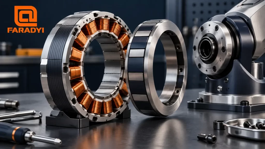
Frameless motor selection starts with the motion your machine needs and the space available to produce it. A motor kit can fit neatly inside a robot joint or rotary axis, but the surrounding mechanics become part of the motor system. Torque, cooling, bearings, and feedback need to be planned together.
Quick answer: Choose a frameless motor by checking continuous and peak torque at the required speed, the available DC bus and drive current, the mechanical envelope, and the installed cooling conditions. Then confirm how the machine will support the rotor, maintain the air gap, measure position, and hold the load when necessary.
What a frameless motor includes
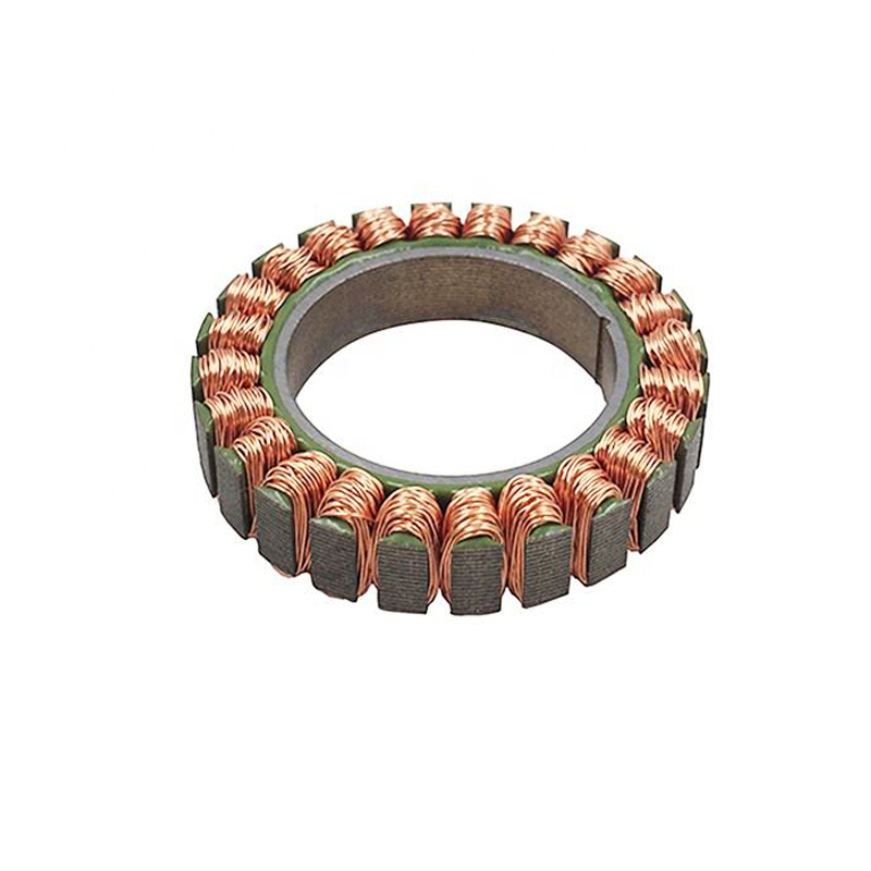
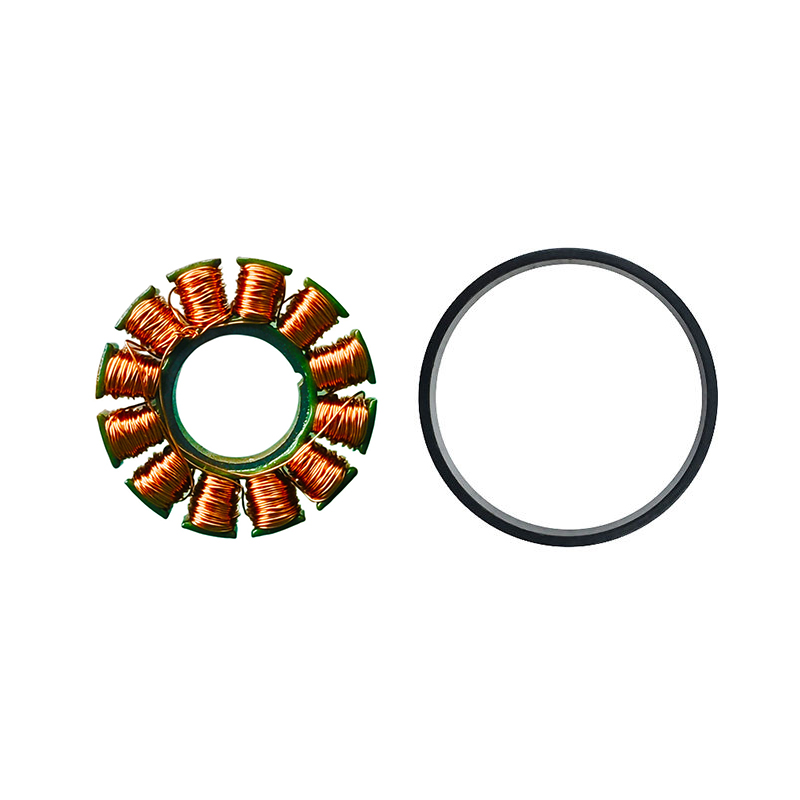
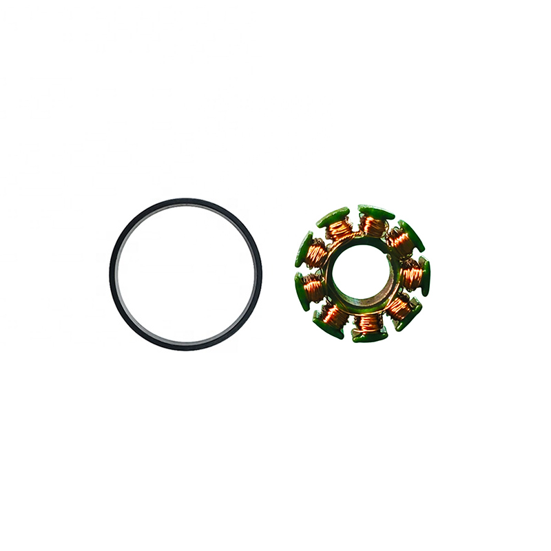
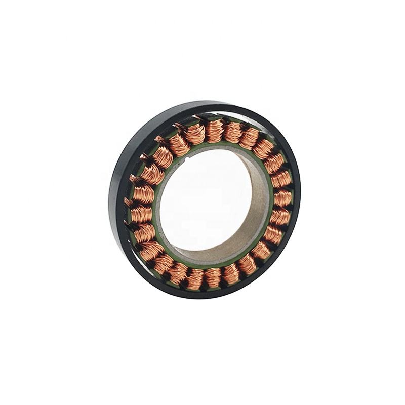
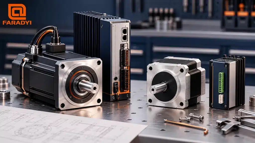
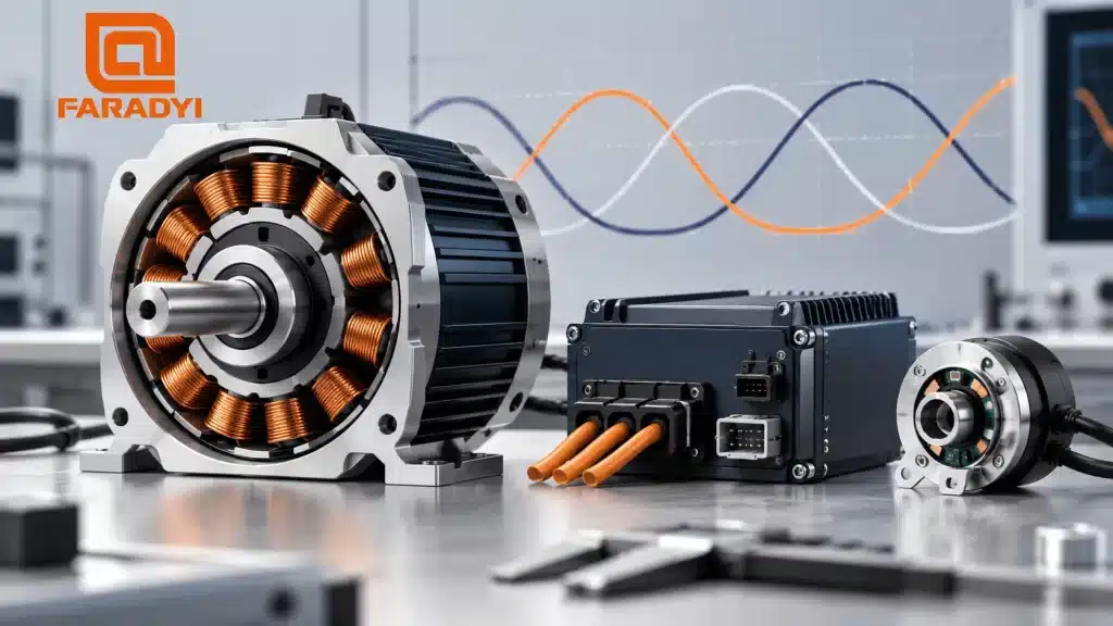
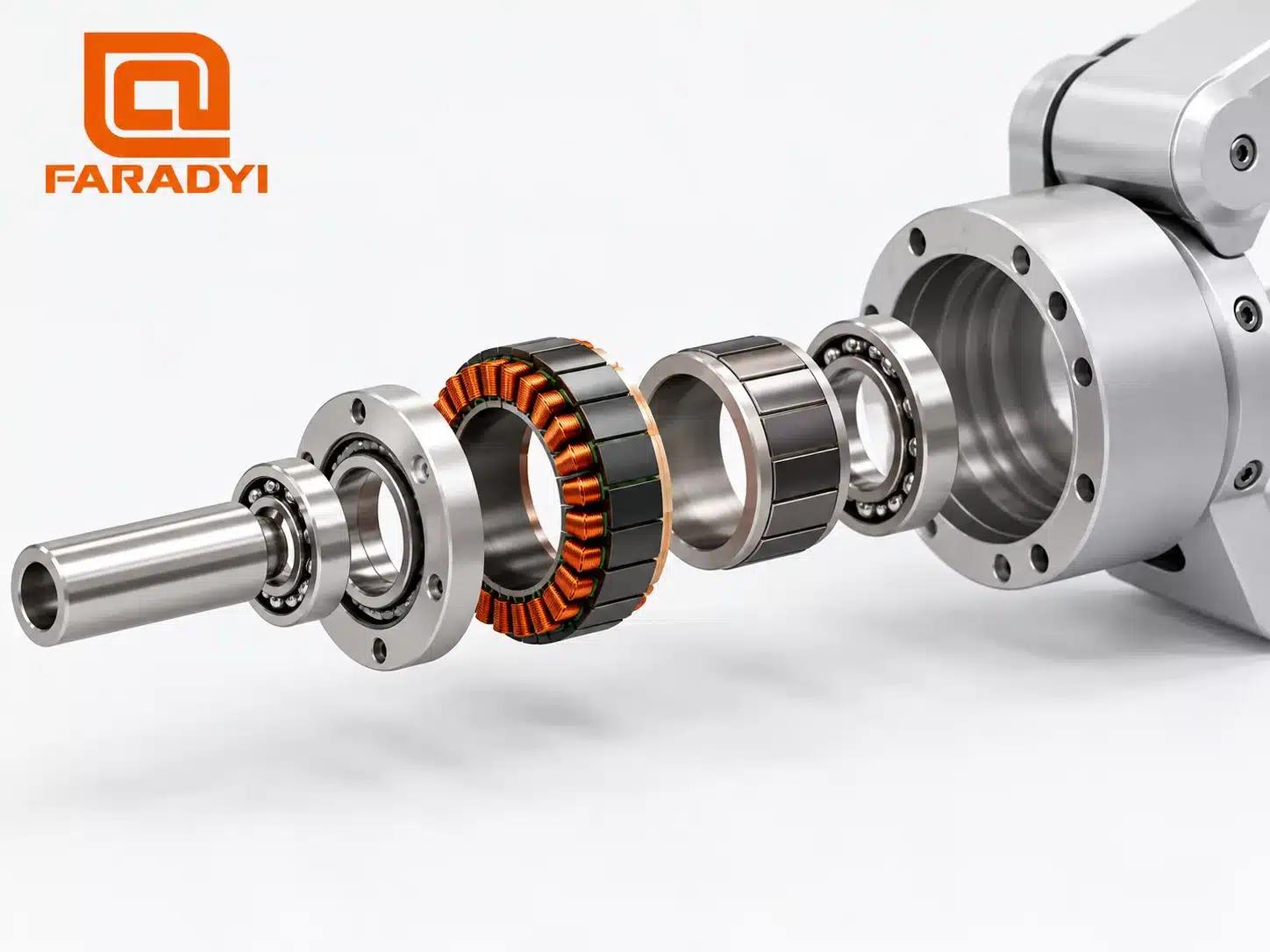
A typical brushless frameless motor kit supplies a wound stator and a permanent-magnet rotor assembly. The stator mounts in the machine structure; the rotor attaches to the rotating member. Unlike a housed motor, the kit normally relies on the machine for its shaft, bearings, and enclosure. Check the scope of supply because sensors, leads, and mounting features vary by model.
This arrangement is useful when a standard motor housing would take up valuable space. It can also create room through the center of a joint for cables or other services. However, a frameless motor does not automatically mean direct drive: the rotor may drive the load directly or work with a transmission.
When the integration work is worthwhile
Consider frameless construction when the machine needs a compact rotary axis, a large central opening, or a motor built around an existing bearing and shaft arrangement. Robot joints, gimbals, rotary stages, and specialized automation axes are common examples.
A housed motor may be the more practical choice when standard mounting, quick replacement, and a short development cycle matter most. Removing the motor housing transfers design work to the machine builder. It does not remove the need for bearings, thermal protection, or maintenance access.
Browse Faradyi’s frameless motor range to compare available formats, then request the drawing and operating data for the specific model. A category description cannot establish the limits of every motor in the range.
Five checks for frameless motor selection
1. Define the complete torque and speed cycle
Write down running speed, acceleration time, load inertia, friction, and any external force. Include reversals, dwell periods, and holding torque. For a simple rotary axis, acceleration torque follows T = J × α, with inertia and acceleration expressed in consistent units. Add the other loads acting on the shaft.
Compare sustained demand with the continuous rating and brief events with the specified peak envelope. Peak torque needs a permitted duration and recovery period. Do not size a repeating process from its highest torque value alone.
2. Match the winding to the drive
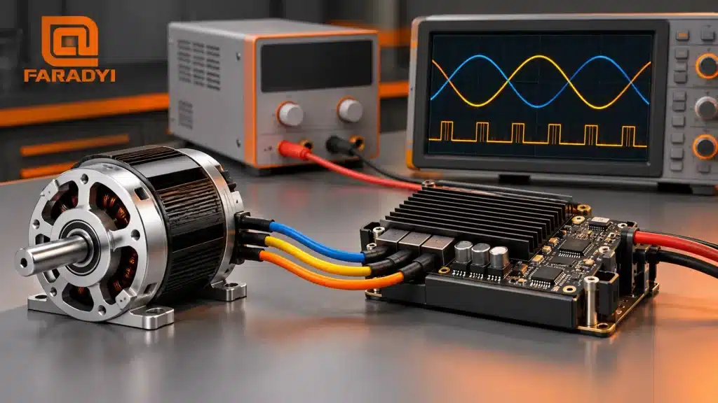
Confirm that the selected winding and drive can deliver the required operating point at the available bus voltage. Current capability, back EMF, winding resistance and inductance, and the drive’s voltage margin all matter. A motor’s maximum mechanical speed is not a promise that it will reach that speed under your load.
Check current definitions before comparing specifications: peak versus RMS and phase versus DC supply measurements are different. Feedback compatibility, commutation setup, and protection functions also belong in the drive review. Our guide to brushless motor vector control explains the role of current regulation and rotor position.
3. Design the heat path
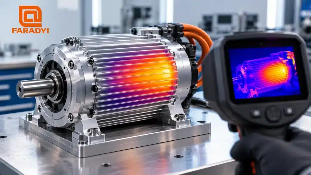
A continuous rating applies under stated thermal conditions. Ask what mounting surface, ambient temperature, airflow, or cooling arrangement was used. A stator fitted into a thermally effective metal structure can behave differently from one inside an insulating enclosure.
Plan temperature sensing and verify the complete axis through its duty cycle. Winding, magnet, adhesive, bearing, and nearby component limits may differ. There is no universal efficiency or safe surface-temperature value for every frameless motor.
4. Check bearings, fits, and assembly access
The mechanical design must carry radial and axial loads while maintaining the specified rotor-to-stator clearance. Review concentricity, runout, thermal expansion, and the supplier’s mounting tolerances. Use the approved retention and assembly method rather than assuming any press fit or adhesive will work.
Leave a practical route for installation, inspection, and removal. Strong permanent magnets can pull components together during assembly, so use the supplier’s handling procedure and suitable tooling.
5. Specify feedback and holding behavior
Choose feedback to suit commutation, positioning, startup, and the operating environment. A Hall sensor, incremental encoder, and absolute encoder provide different information. Sensor resolution is only one part of axis accuracy; mounting, calibration, stiffness, and transmission errors remain relevant.
If an axis can move dangerously when power is removed, specify a suitable holding and safety strategy. Motor torque or a position loop alone does not establish safe load retention. Medical or aerospace use also requires application-specific qualification; motor construction by itself is not certification.
Frameless versus housed motor: practical tradeoffs
On a phone, swipe horizontally to read the table.
| Design question | Frameless motor | Housed motor |
|---|---|---|
| Mechanical integration | Built into the machine’s rotating structure | Usually attaches through standard mounting features |
| Bearing support | Designed as part of the machine | Typically included, within specified shaft-load limits |
| Thermal installation | Machine housing and mounting strongly influence cooling | Still depends on the specified mounting and environment |
| Service | Removal may involve dismantling the axis | Replacement is often simpler when access is planned |
| Best reason to choose | Integration solves a real packaging or axis-design need | A standard complete motor meets the application |
Prepare a useful engineering inquiry
For example, a joint that holds a load for most of its cycle needs a different review from a rotary stage that runs continuously. Describe that operating pattern before requesting a frame size.
Send Faradyi your bus voltage, loaded speed, continuous and peak torque with durations, duty cycle, available diameter and axial length, required bore, bearing arrangement, cooling conditions, feedback needs, and expected quantity. Include an assembly sketch when possible.
You can start with the robot joint motor collection ou contact Faradyi for a motor selection review. Ask which supplied configuration and test conditions match your design.
Frequently asked questions
Does a frameless motor need a separate controller?
The motor needs a compatible drive to energize its windings. A separate motion controller may also be used, depending on the drive’s functions and the machine architecture.
Are frameless motors always more efficient or quieter?
No. Compare the actual operating point and complete assembly. Motor losses, control waveforms, cooling, bearings, and any gearing affect the result.
Can a frameless motor drive a gearbox?
Yes. Frameless construction describes the motor’s packaging. The required output torque, speed, stiffness, and space determine whether a transmission is useful.
Choose the motor and the installation together
Good frameless motor selection connects the electrical operating point to a workable mechanical and thermal design. Confirm those interfaces before committing to a motor diameter or peak-torque figure, and validate the assembled axis under its intended load cycle.
Technical references