Introduction
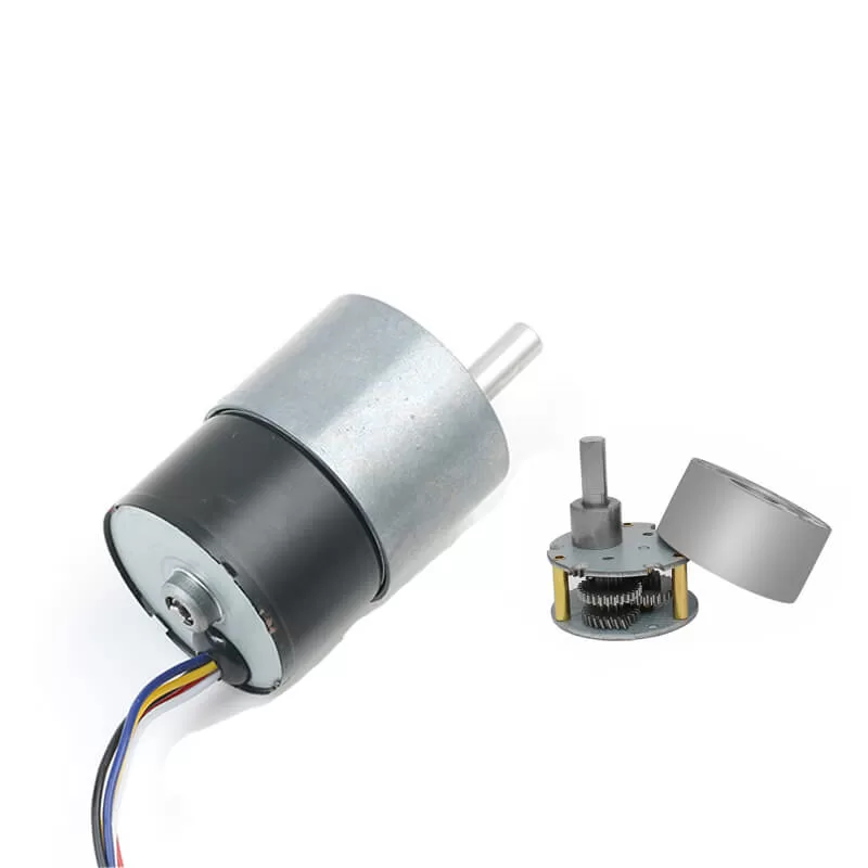
Stepper motors convert electrical pulse signals into corresponding angular or linear displacements. With each input pulse signal, the rotor rotates by a certain angle or moves forward one step. The output angular or linear displacement is proportional to the number of input pulses, and the speed is proportional to the pulse frequency. Therefore, stepper motors act as components that convert pulses into angular (or linear) displacements.
Stepper motors have a multi-pole distributed rotor and stator with multiple-phase star-connected control windings. Each input pulse signal causes the stepper motor’s rotor to advance one step. Since the input is a pulse signal, the output angular displacement is discontinuous, hence the name “pulse motor.”
With the development of digital control systems, the application of stepper motors will gradually expand. Stepper motors come in various types, including reactive, excitation, and hybrid, based on their structure, and can be classified into single-phase, two-phase, and multi-phase based on the number of phases.
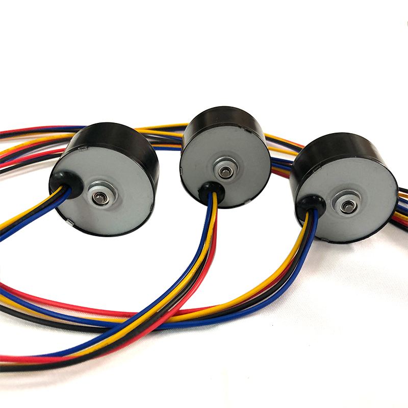
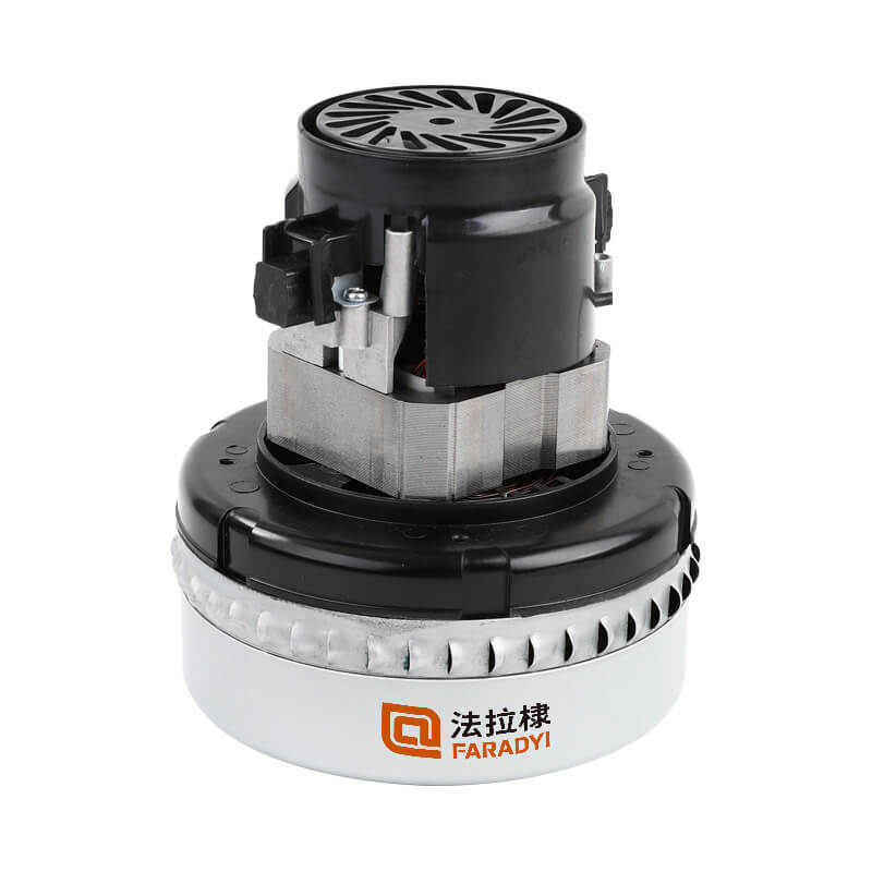
Low Voltage DC Servo Motor
Low voltage DC servo motors can be understood as motors that strictly follow control signal commands: the rotor remains stationary until a control signal is issued; upon signal emission, the rotor immediately rotates; and when the control signal disappears, the rotor stops instantly.
Low voltage DC servo motors are micro motors used as actuating components in automatic control devices, converting electrical signals into angular displacements or angular velocities of the shaft. Their main features include: no self-rotation when the signal voltage is zero, a decrease in speed with increasing torque, and highly accurate control of speed and position.
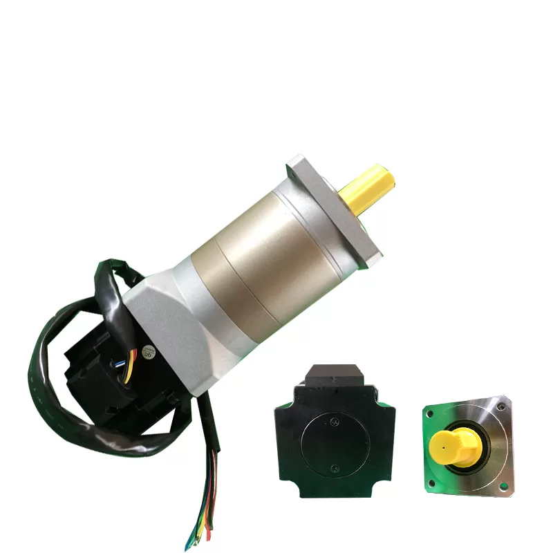
The basic structure of low voltage DC servo motors is similar to that of general DC motors.
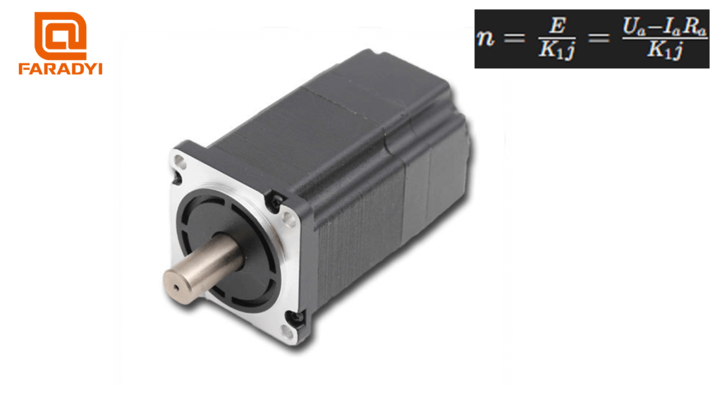
The motor speed n is given by the formula:
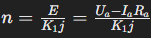
where E is the armature back electromotive force, K is a constant, j is the per-pole flux, Ua and, Ia are the armature voltage and current, and Ra is the armature resistance. Changing Ua or ϕ can control the speed of the low voltage DC servo motor. However, the method of controlling the armature voltage is generally adopted. In permanent magnet low voltage DC servo motors, the excitation winding is replaced by permanent magnets, keeping the magnetic flux ϕ constant. Low voltage DC servo motors have good linear adjustment characteristics and fast response times.
Comparison of Performance Characteristics between Low Voltage DC Servo Motors and Stepper Motors:
While both stepper motors and low voltage DC servo motors have similarities in control methods (pulse trains and direction signals), there are significant differences in their performance and application scenarios. Let’s compare their performance characteristics:
Difference in Control Precision:
-
- Number of Phases in Stepper Motors: This refers to the number of coil groups inside the motor. Commonly used stepper motors have two-phase, three-phase, four-phase, and five-phase configurations. Different phase numbers correspond to different step angles. For example, two-phase motors typically have step angles of 0.9°/1.8°, three-phase motors have 0.75°/1.5°, and five-phase motors have 0.36°/0.72°. When there is no subdivided driver, users mainly choose stepper motors with different phase numbers to meet their step angle requirements. With a subdivided driver, the “phase number” becomes meaningless, as users can change the step angle by changing the subdivision number on the driver.
- Control Precision of Low Voltage DC Servo Motors: This is ensured by the rotary encoder at the rear end of the motor shaft. For motors equipped with standard 2500-line encoders, due to the driver’s use of quadrupling technology, the pulse equivalent is 360°10000=0.036°10000360°=0.036°. For motors with 17-bit encoders, the driver receives 131,072 pulses per motor revolution, resulting in a pulse equivalent of 360°131072=0.0027466°131072360°=0.0027466°, which is 1/655 of the pulse equivalent of a stepper motor with a step angle of 1.8°.
Difference in Low-Frequency Characteristics:
-
- Low-Frequency Vibration in Stepper Motors: Stepper motors are prone to low-frequency vibration at low speeds. The vibration frequency depends on the load condition and driver performance. The vibration frequency is typically half of the motor’s no-load starting frequency. This low-frequency vibration, determined by the operating principle of stepper motors, is highly detrimental to normal machine operation. When stepper motors operate at low speeds, damping techniques such as adding dampers to the motor or using subdivision technology in the driver are usually employed to overcome low-frequency vibration.
- Stable Operation of Low Voltage DC Servo Motors: Low voltage DC servo motors operate smoothly, with no vibration even at low speeds. Low voltage DC servo systems feature resonance suppression capabilities, covering mechanical rigidity deficiencies. Additionally, the system has frequency analysis capabilities (FFT) internally, capable of detecting mechanical resonance points, facilitating system adjustments.
Difference in Torque-Frequency Characteristics:
-
- Output Torque of Stepper Motors: The output torque of stepper motors decreases with increasing speed and sharply drops at higher speeds. Therefore, their maximum operating speed is generally between 300 and 600 RPM.
- Constant Torque Output of Low Voltage DC Servo Motors: Low voltage DC servo motors provide constant torque output and can deliver rated torque at speeds above rated speed, providing constant power output.
Difference in Overload Capacity:
Stepper motors generally do not have overload capacity. Low voltage DC servo motors have strong overload capacity.
Low voltage DC servo motors have speed and torque overload capabilities. Their maximum torque is three times the rated torque and can be used to overcome the inertia torque of the load at startup.
Stepper motors lack this overload capacity. Therefore, to overcome this inertia torque, a stepper motor with a larger torque is often selected, resulting in wasted torque during normal machine operation.
Difference in Operational Performance:
-
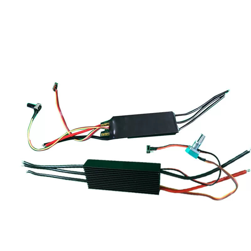
- Control of Stepper Motors: Stepper motors operate under open-loop control. High startup frequencies or excessive loads can lead to missed steps or motor stalling. When stopping, high-speed rotation can lead to overshoot. Therefore, to ensure control accuracy, the issues of acceleration and deceleration should be handled properly.
- Control of Low Voltage DC Servo Systems: Low voltage DC servo drive systems operate under closed-loop control. The driver can directly sample the motor encoder feedback signal, internally forming a position loop and a velocity loop, thus avoiding the missed steps or overshoot phenomena associated with stepper motors, and ensuring more reliable control performance.
Difference in Speed Response Performance:
-
- Stepper Motors: It takes 200-400 milliseconds for stepper motors to accelerate from standstill to operating speed (typically several hundred revolutions per minute).
- Low Voltage DC Servo Systems: Low voltage DC servo systems have excellent acceleration performance, requiring only a few milliseconds to accelerate from standstill to their rated speed of 3000 RPM, making them suitable for control applications requiring rapid start