DM542 Stepper Motor Driver

Feature:

Product Overview

DM542 DSP control of the digital two-phase hybrid stepper motor driver, suitable for the phase current in 4.2 Abelow, 0D 39, 42, 57, 60, 86 mm four, six, eight-wire two-phase hybrid stepper motor. Can be set in 128 various subdivisions and 4.2A various currents, internal increase motor dedicated control algorithm, can be used ford ifferent motor corresponding operating parameters, so that the motor running very smooth, vibration an dnoise is min imal. Built-in overheat, overcurrent, overvoltage detection to protect the stable operation of the drive

Application Field

Suitable for various automation equipment and instruments in the field of motion control, such as: 3D printers, laser processing equipment, engraving equipment, medical equipment, measuring equipment, electronic processing equipment, textile and clothing equipment, etc. It is used in equipment where users expect low vibration and low noise, and is the first choice in areas with strong cost-effective competition.

Interface Definition

Control signal interface

Name Function
PUL+
PUL-
Pulse input signal
The pulse effective edge is adjustable, and the default pulse rising edge is effective; in order to reliably respond to the pulse signal, the pulse width should be greater than 1.2us. 5-24VDC level compatible.
DIR+
DIR-
Direction input signal
High/low level signal, to ensure reliable commutation of the motor, the direction signal should be established at least 5us before the pulse signal. The initial running direction of the motor is related to the motor winding connection. Interchanging any phase winding (such as A+ and A- exchange) can change the initial running direction of the motor. 5-24VDC level compatible.
ENA+
ENA-
Enable control signal
This input signal is used to enable or disable the driver output. When ENA is connected to a low level (or the internal optocoupler is turned on), the driver will cut off the current of each phase of the motor to make the motor in a free state and not respond to step pulses. When this function is not needed, the enable signal end can be left floating. 5-24VDC level compatible.

Model:

其他信息

Thanks for sharing it !

Proudct Information:

Description

1.Parameter setting

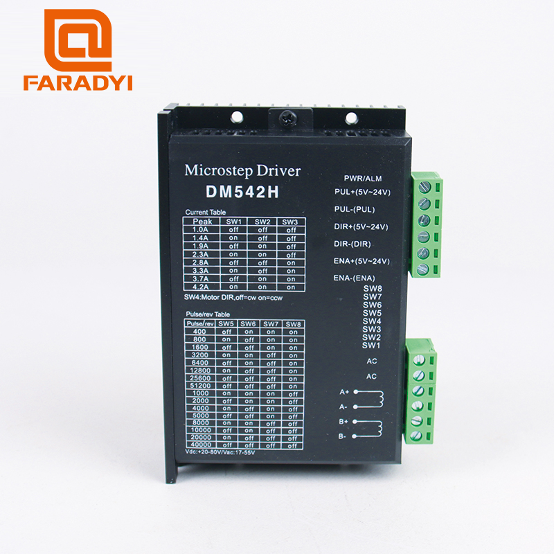
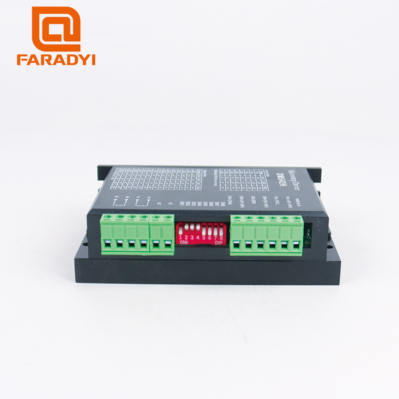
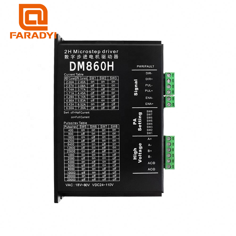
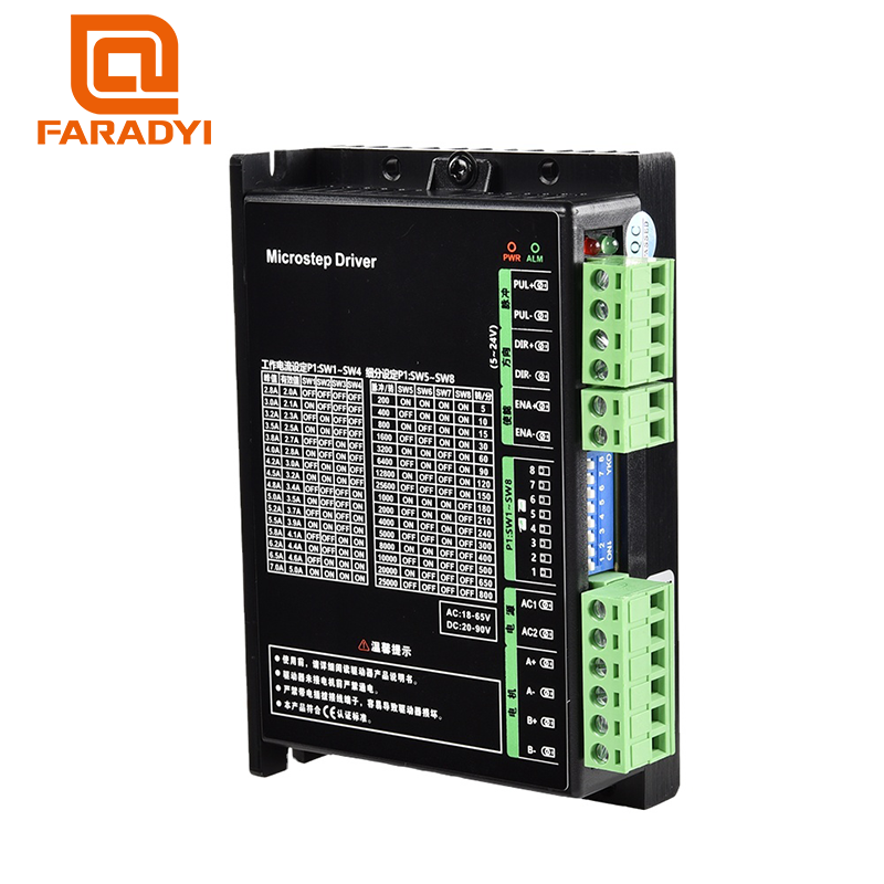
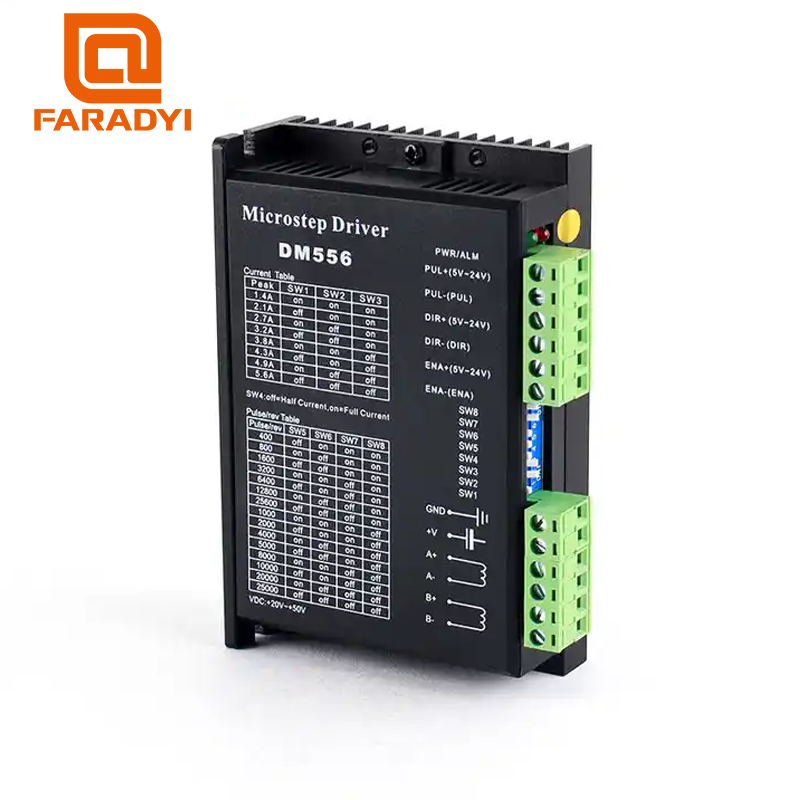
The driver uses an eight-position DIP switch to set dynamic current, full current/half current, and subdivision accuracy. The detailed description is as follows:

Control function Running current Standby current Subdivision accuracy
DIP switch position SW1, SW2, SW3 SW4 SW5, SW6, SW7, SW8

Running current setting

Running current SWI sw2 sw3
1. 00A ON ON ON
1.46A OFF ON ON
1. 91A ON OFF ON
2.37A OFF OFF ON
2.84A ON ON OFF
3.31A OFF ON OFF
3.76A ON OFF OFF
4.20A OFF OFF OFF

Standby current setting

SW4 ON full flow mode
OFF half flow mode

Subdivision accuracy setting

Subdivision accuracy Pulse number/circle sw5 sw6 sw7 sw8
2 400 OFF ON ON ON
4 800 ON OFF ON ON
8 1600 OFF OFF ON ON
16 3200 ON ON OFF ON
32 6400 OFF ON OFF ON
64 12800 ON OFF OFF ON
128 25600 OFF OFF OFF ON
5 1000 ON ON ON OFF
10 2000 OFF ON ON OFF
20 4000 ON OFF ON OFF
25 5000 OFF OFF ON OFF
40 8000 ON ON OFF OFF
50 10000 OFF ON OFF OFF
100 20000 ON OFF OFF OFF
125 25000 OFF OFF OFF OFF

2.Control signal wiring diagram

wiring connection stepper drive

3.Overall installation dimensions

Overall installation dimensions

4.Operating environment and parameters

Cooling method Natural cooling or forced air cooling
Use environment Occasion Avoid dust, oil, corrosive gas, high humidity and strong vibration. Combustible gas and conductive dust are prohibited.
temperature 0℃—50℃
Humidity 40-90%RH
Vibration 10-55Hz/0.15mm
Storage temperature -20℃—65℃
Weight 0.25kg


Faradyi Motors Service

How to use the motor

1. Use tolerance: pay attention to the use range of voltage and current, and use the motor under the conditions specified in this standard, otherwise the life of the motor will be reduced.
2. Handling the motor: handle it with care, and use the motor casing as much as possible.
3. Motor wiring: the red lead wire is connected to the positive pole, and the black lead wire is connected to the negative pole. If the connection is reversed, the motor will rotate in the opposite direction.
4. Overload: Use it within the specified load range as much as possible. It is strictly forbidden to run the motor in a stalled state or close to the stalled state for a long time, otherwise the motor will burn out.
5. Motor storage:Storage temperature: 0C-40°C, storage humidity: 15%-90% RH
Avoid placing it in an environment with high temperature, high humidity and corrosive gas.
6. Motor operating temperature: 0°C-70C

Motor Precautions

1. When you use the motor, there must be no binding objects, such as adhesive, do not flow into the bearing through the rotating shaft, which will hinder the operation of the motor.
2. The rotation of the shaft may have the opposite effect on the life of the motor. In order to prolong the life, please check whether your load is in accordance with the regulations. Do not overload or hang items that hinder the rotation of the shaft.
3. Manufactured into an eccentric heavy radiation load, harmful to the life of the motor.
4. Do not store it in high temperature or extreme humidity, and do not place it in corrosive gas, which will reduce the effect of the motor
5. Do not run the motor in the surrounding high temperature and humidity.
6. When soldering on the positive and negative motor terminals of the power supply, the temperature of the soldering iron is 340C40C, and the heating time is within 3 seconds. Do not deform the plastic. Let the solder point flow into the motor or break the end of the wire during work, which will make the motor function decline.
7. Do not let the motor shaft get stuck. When the power is supplied, the motor will overheat in a short time and burn its accessories.
8. Supply the specified power and make sure it is within the range of measurable requirements.
9. When installing pulleys or gears, do not increase the weight abnormally when pressing them in.
10. When installing the motor, if the screw is too long, it will cause contact between the motor itself and the
rotor, which will affect the characteristics.

Related Products

Submit a Quick Quote

Don't Take Our Word for It - See What Customers Say

We strive to provide exceptional products and service. If you are satisfied with your experience, we would greatly appreciate you taking a moment to leave us a review

en_USEnglish

Product Inquiry

Product Inquiry