- (+086) 18923470557
- [email protected]
- 7F, No.53 Fofu Road, Dalang Town, Dongguan City, Guangdong, CN,523770


 |
|
 |
|
|
MARKED SYMBOL
|
FUNCTION
|
CONDITIONAL COMMENT
|
|
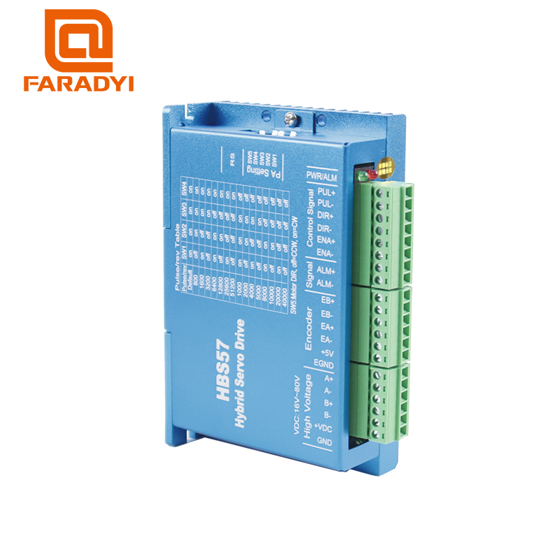
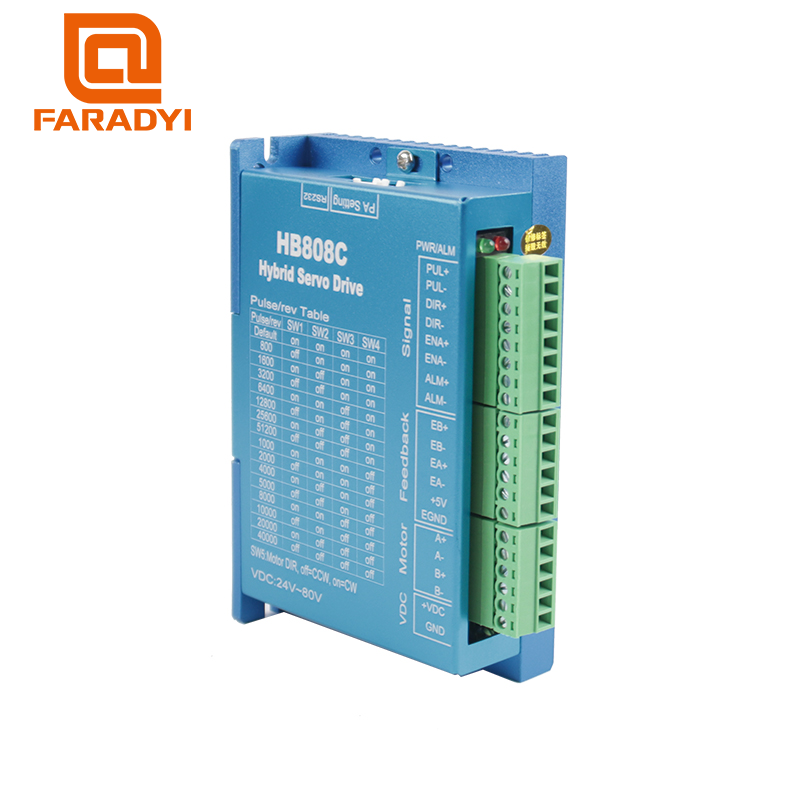
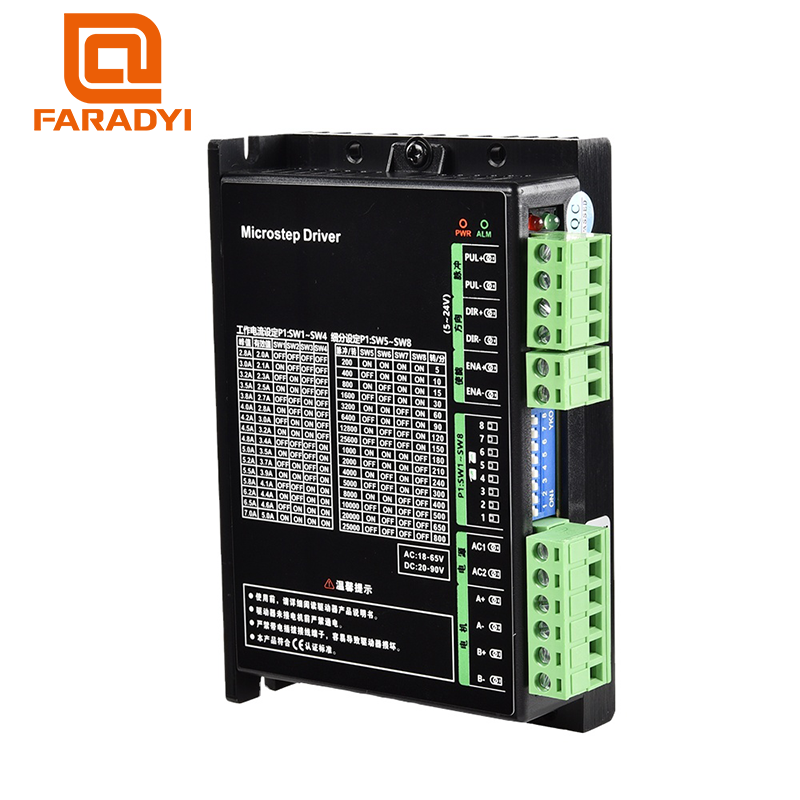
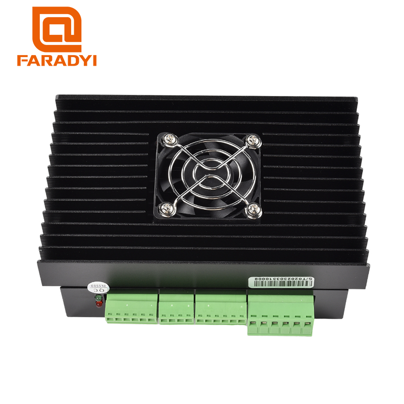
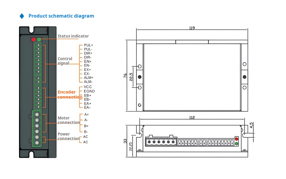
PWR/FLT
|
Voltage and fault indicator
|
Green flashing: the driver is normal, no pulse signal is received: green steady on: pulse signal is received, the motor rotates;One red and one green: overcurrent or interphase short-circuit fault; Two red and one green: No motor or motor wiring error detected; Three red and one green: overvoltage fault; Four red and green: undervoltage fault, five red and green: tracking error overerror fault
|
|
PUL+
|
Pulse input signal photoelectric isolation positive end
|
Pulse signal voltage 3.3~24V can be driven
|
|
PUL-
|
Pulse input signal photoelectric isolation negative end
|
The falling edge is effective, and the motor takes a step whenever the pulse changes from high to low. Pulse width greater than 2.5 microseconds
|
|
DIR+
|
Direction input signal photoelectric isolation positive end
|
Direction signal voltage 3.3~24V can be driven
|
|
DIR-
|
Direction input signal photoelectric isolation negative end
|
Used to change motor steering. The falling edge is effective, and the motor takes a step whenever the pulse changes from high to
low. Pulse width greater than 2.5 microseconds |
|
EN+
|
The positive end of the input signal was enabled
|
Enable signal voltages from 3.3 to 24V can be driven
|
|
EN-
|
The negative end of the input signal was enabled
|
When effective (low level) turn off the motor coil current, the motor is in the free state and clear the alarm signal
|
|
EX+
|
Position signal output positive end
|
When the driver completes the given pulse, the position signal is effective (output optocoupler conduction). EX+ connects the pull
resistor to the positive terminal of the output power supply, and EX- connects to the negative terminal of the output power supply. The maximum driving current is 10mA. |
|
EX-
|
Position signal output negative end
|
|
|
ALM+
|
Alarm signal output positive end
|
When the red light blinks, the alarm signal is effective (output optocoupler conduction). ALM+ connects the pull resistor to the
positive terminal of the output power supply, and ALM- connects to the negative terminal of the output power supply. The maximum driving current is 10mA. |
|
ALM-
|
Alarm signal output negative end
|
|
|
VCC
|
Encoder power positive
|
Encoder 5V power supply positive end
|
|
EGND
|
encoelectrically
|
encoelectrically
|
|
EB+
|
Encoder B phase input positive end
|
Encoder B channel positive input
|
|
EB-
|
Encoder B phase input negative end
|
Encoder B channel negative input
|
|
EA+
|
Encoder phase A input positive end
|
Encoder A channel positive input
|
|
EA-
|
Encoder A phase input negative end
|
Encoder A channel negative input
|
|
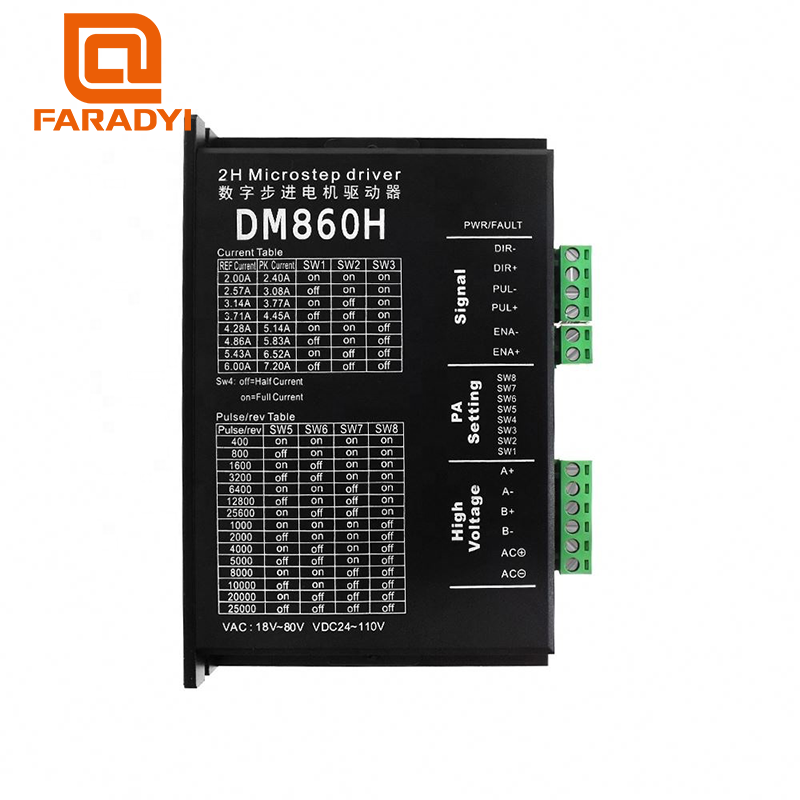
A+
|
Motor wiring A+
|
|
|
A-
|
Motor wiring A-
|
|
|
B+
|
Motor wiring B+
|
|
|
B-
|
Motor wiring B-
|
|
|
AC1
|
Driver power supply
|
Voltage range: AC18~AC80V/DC20~DC110V
|
|
AC2
|
Driver power supply
|
| Cooling method | Natural cooling or forced air cooling | |
| Use environment | Occasion | Avoid dust, oil, corrosive gas, high humidity and strong vibration. Combustible gas and conductive dust are prohibited. |
| temperature | 0℃—50℃ | |
| Humidity | 40-90%RH | |
| Vibration | 10-55Hz/0.15mm | |
| Storage temperature | -20℃—65℃ | |
| Weight | 0.25kg | |