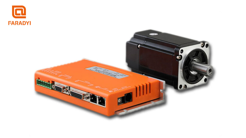
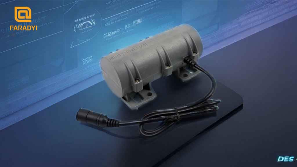
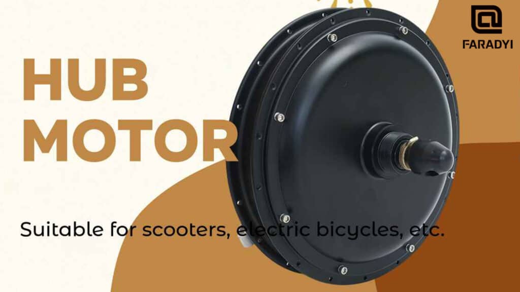
A servo feed system is an automatic control system that uses the position and speed of moving parts as control variables. It is a typical electromechanical integrated system, mainly composed of position control unit, speed control unit, drive component (motor), detection and feedback unit, and mechanical execution unit.
Requirements of Servo Feed Control Systems:
Fast response without overshoot.
Wide speed range.
High positioning accuracy.
Sufficient transmission rigidity and high speed stability.
High reliability, with the feed drive system of CNC machine tools being highly reliable, stable in operation, adaptable to temperature, humidity, vibration, and other environmental conditions, and highly resistant to interference.
Low-speed high torque, strong overload capacity. Generally, servo drives have an overload capacity of several times or even several times within a few minutes or even half an hour without damage.
Requirements for Servo Motors:
The motor should withstand frequent start, brake, and reverse operations.
The motor should operate smoothly at both high and low speeds, with minimal torque fluctuations. Especially at low speeds, it should maintain a steady speed without crawling.
The motor should have a large and long-lasting overload capacity to meet the requirements of low-speed high torque. Generally, DC servo motors are required to withstand an overload of 4-6 times without damage within a few minutes.
To meet the requirements of fast response, the motor should have a small moment of inertia, a large stall torque, and as small a time constant and starting voltage as possible.
Relevant Parameters of Servo Amplifiers:
1. Position Proportional Gain:
- Set the proportional gain of the position loop regulator.
- The parameter value is determined by the specific servo system model and load conditions.
- A larger setting results in higher gain and stiffness, leading to smaller position lag under the same frequency command pulse conditions. However, setting the value too high may cause oscillation or overshoot.
2. Position Feedforward Gain:
- Set the feedforward gain of the position loop.
- A larger setting indicates smaller position lag under any frequency command pulse conditions.
- This parameter is usually set to 0 when there is no need for high response characteristics.
- A larger feedforward gain in the position loop improves the high-speed response characteristics of the hydraulic servo control system, but can make the system unstable and prone to oscillation.
3. Speed Proportional Gain:
- Set the proportional gain of the speed regulator.
- Set the value as large as possible under the condition that the system does not oscillate.
- A larger setting results in higher gain and stiffness. The parameter value is determined by the specific servo drive system model and load value. In general, the larger the load inertia, the larger the setting value.
4. Speed Integral Time Constant:
- Set the integral time constant of the speed regulator.
- Set the value as small as possible under the condition that the system does not oscillate.
- A smaller setting results in faster integral speed. The parameter value is determined by the specific servo drive system model and load conditions. In general, the larger the load inertia, the larger the setting value.
5. Speed Feedback Filter Factor:
- Set the low-pass filter characteristics of the speed feedback.
- A smaller value results in a higher cutoff frequency and faster speed feedback response.
- A larger value results in a lower cutoff frequency and less motor noise. If the load inertia is large, the setting value can be appropriately reduced. A value that is too large will slow down the response and may cause oscillation.
6. Peak Output Torque Setting:
- Independent of the rotation direction.
- Set to reach speed.
- Set the internal torque limit value of the servo motor.
- The setting value is a percentage of the rated torque.
- This limit is valid in the positioning completion range at any time.
- Set the positioning completion pulse range in the positioning control mode.
- The acceleration and deceleration characteristics are linear in the speed range to reach the speed.
- In the positioning control mode, if the motor speed exceeds this setting value, the speed arrival switch signal is ON; otherwise, it is OFF.
- This parameter provides the basis for the driver to judge whether the positioning is completed in the positioning control mode. When the remaining pulses in the position deviation counter are less than or equal to the setting value, the driver considers the positioning completed, and the in-place switch signal is ON; otherwise, it is OFF.
For inquiries or assistance with servo control systems and related solutions, contact Faradyi Technology Co., Ltd, a leading high-tech enterprise specializing in the development and production of high-performance, high-quality DC brushless motors, stepper motors, and associated driver controllers for global industrial automation.
