Gear reducers are mechanical devices that utilize gears to reduce the speed of rotation (RPMs) from a power source while increasing the torque. They allow motors and engines that operate at high speeds to deliver usable power output for various industrial and vehicle applications.
What is a Gear Reducer and How Does it Work?
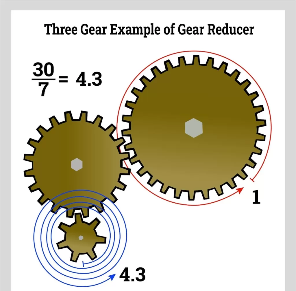
A gear reducer consists of a set of interlocking gears of different sizes mounted on shafts. One small drive gear engages with a larger driven gear. Due to the size difference, the drive gear must rotate multiple times to turn the driven gear once. This step-down of speed produces gear reduction.
The gear ratio determines the amount of reduction. It is calculated by comparing the number of teeth on the drive gear to the teeth on the driven gear. For example, if the drive gear has 10 teeth and the driven gear has 40 teeth, the ratio would be 1:4. This means for every 1 rotation of the drive gear, the driven gear only rotates 0.25 times. The output speed is reduced by 75% but torque is multiplied by 4X.
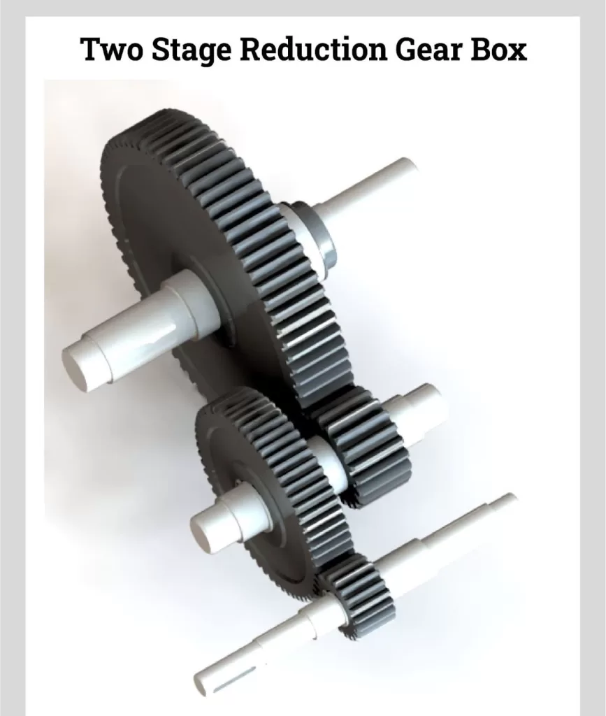
Multiple gear pairs can be used in sequence to achieve very high gear reduction ratios. A compound gear train with a ratio of 1:10 on each stage will produce an overall reduction of 1:100. While input speed drops exponentially, torque increases proportionately with each gear set added.
Gear reducers convert high RPM rotational energy into increased torque at lower speeds usable for the intended application. Careful selection of the gear ratio allows precise matching of the power source to the speed and torque requirements of the machinery being driven.
Types of Gear Reducers
Many different types of gear reducers exist, each with advantages for certain applications:
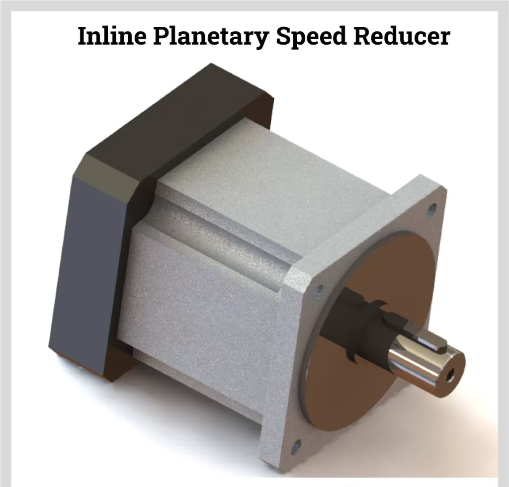
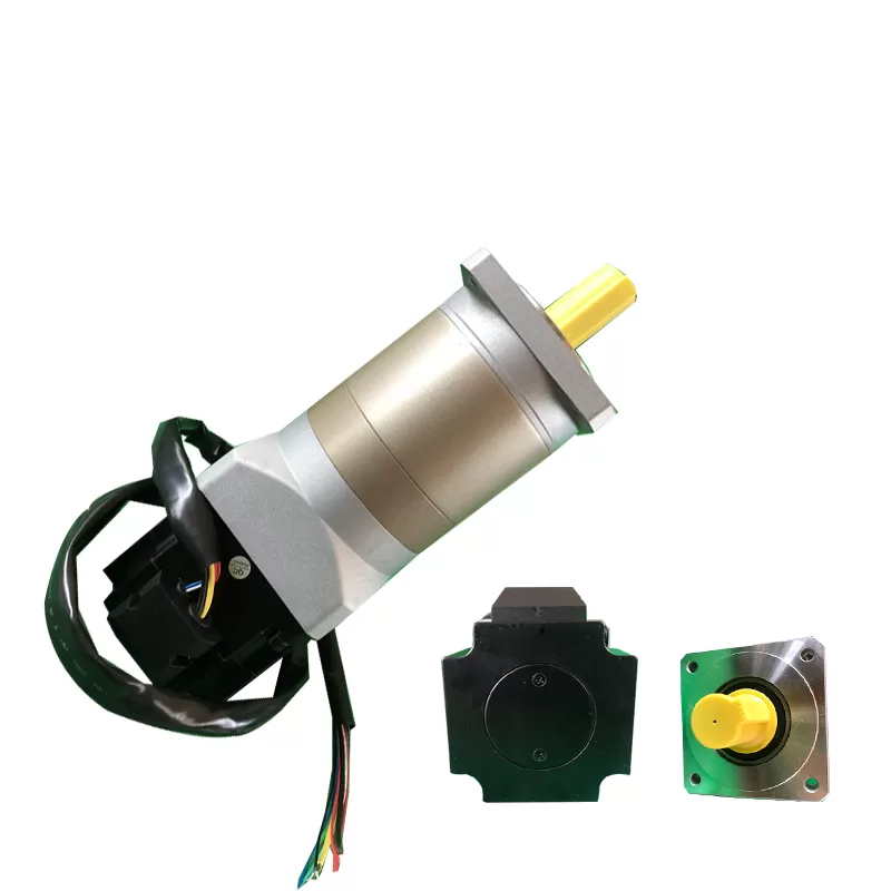
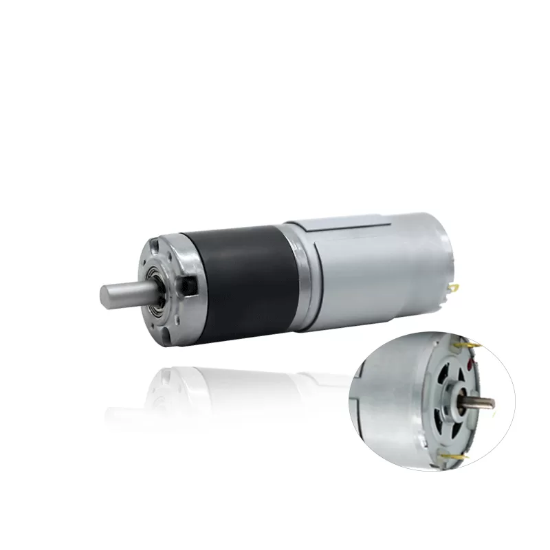
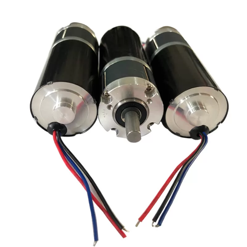
- Planetary Gear Reducers: Planetary gears consist of a sun gear in the center surrounded by smaller planet gears contained in a ring gear. The compact concentric design provides very high torque output in a small package ideal for low speed requirements. These are commonly used in machine tools, robotics, and other precision machinery.
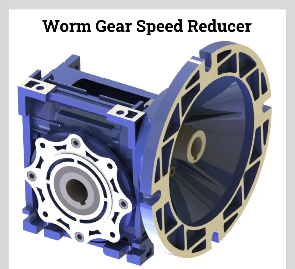
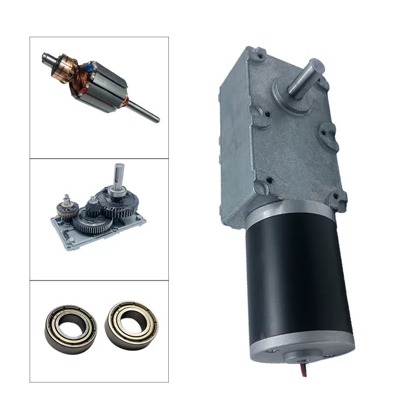
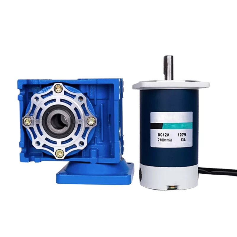
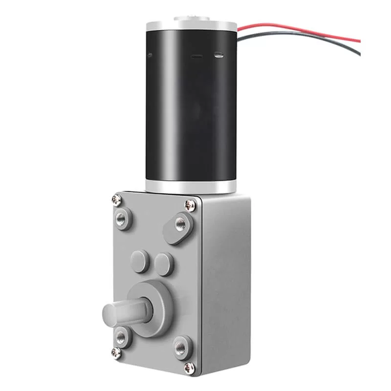
- Worm Gear Reducers: Worm gears use a screw-shaped worm drive gear that engages perpendicularly with a worm wheel. This configuration permits high gear reduction ratios up to 60:1 or greater in a compact space. Worm gears are self-locking, making them useful when reversibility is not required. They are commonly used to control conveyors, hoists, presses, and other machinery.
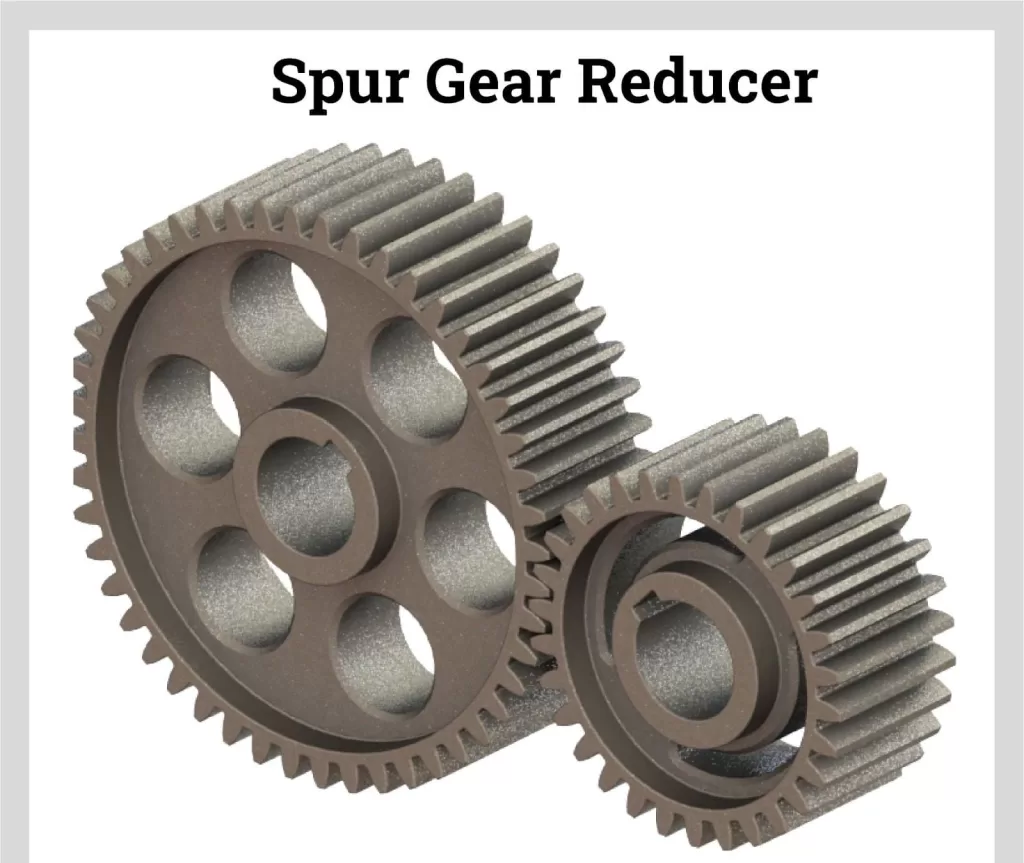
- Spur Gear Reducers: Spur gears have straight teeth cut parallel to the shaft axis. They provide simple, efficient gear reduction through multiple gear stages and are good for very high-speed applications. Spur gears are the most common type of gear reducer used across many industries.
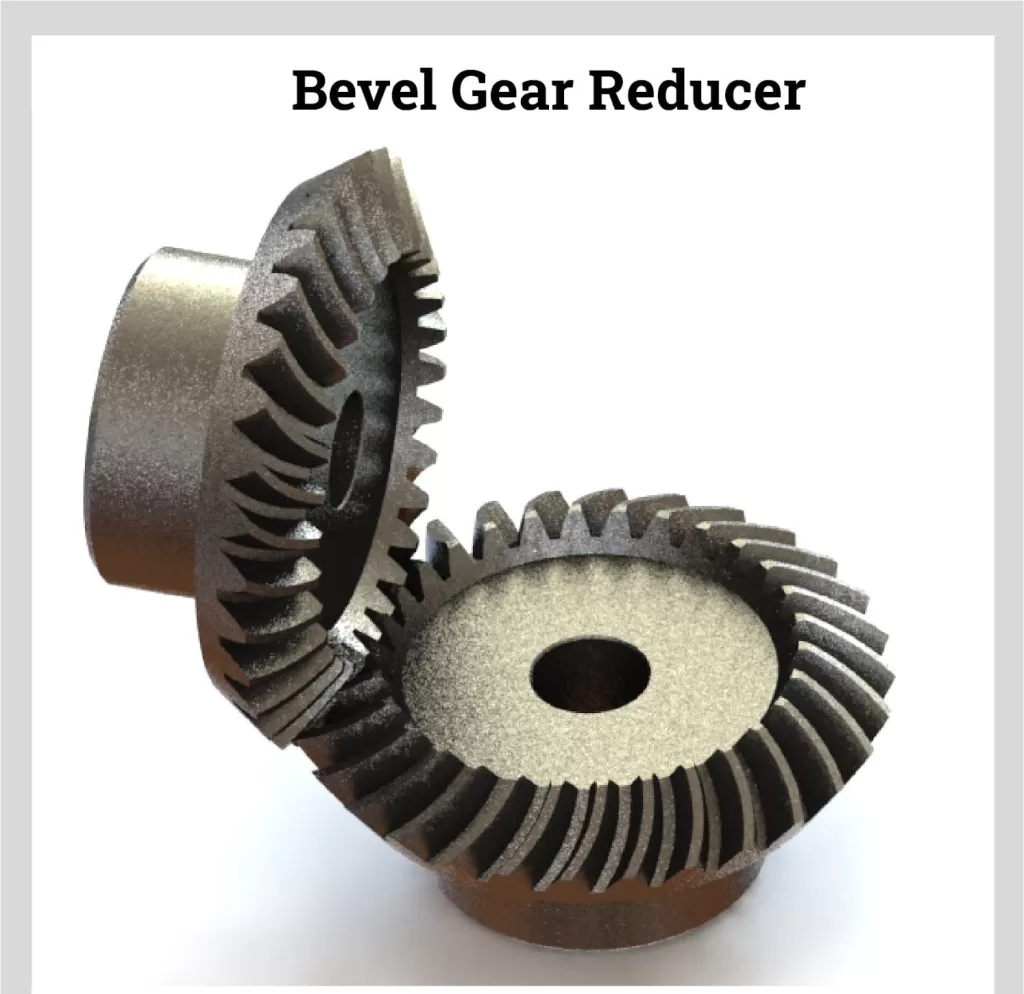
- Bevel Gear Reducers: Bevel gears have conically shaped teeth cut at an angle allowing power transfer between intersecting shafts. Bevel gear reducers are best suited for low ratio speed reduction and can handle very high power throughput. They are often used in agricultural machinery, mining equipment, and other heavy-duty machinery.
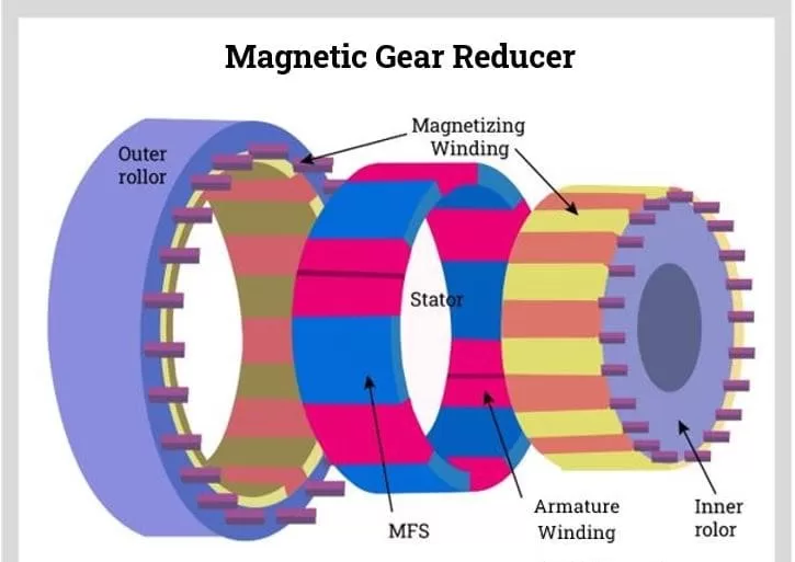
- Magnetic Gear Reducers: These contactless magnetic gears use magnets instead of cut teeth to transmit torque. The benefits are no contact wear and no need for lubrication. Magnetic gears can turn at very high RPMs with precision and are used in sensitive equipment like robotics.
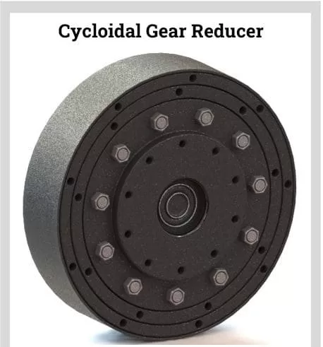
- Cycloidal Gear Reducers: Cycloidal drives use a cycloidal disc that engages eccentrically with a roller gear system. This eccentric roller engagement essentially eliminates backlash, permitting very high precision positioning ideal for machine tools and robotics.
Choosing the Right Gear Reducer
Several factors should be considered when selecting a gear reducer for an application:
- Required torque capacity
- Input speed and desired output speed
- Overall efficiency and precision needed
- Shock loads, cyclic loads, or other motor performance factors
- Mounting configuration (shaft, flange, foot, etc)
- Environmental conditions like dust, water, temperature extremes
Consulting with a qualified engineer is recommended to properly match the gear type, ratio, and features to the application. The gear reducer must be robust enough to handle expected loads throughout the service life without premature wear or failure.
Maintaining Gear Reducers
Like any machinery, proper maintenance is required for gear reducers to achieve maximum performance and longevity. Follow the manufacturer’s specifications for lubricant selection and change intervals. Periodically inspect for any contamination from dust or moisture that may accelerate wear. Listen for abnormal noise or vibration and check for overheating, as these indicate potential problems. Keep stored gear reducers sealed and rotate shafts periodically to coat all internal components with oil. Investing in the right gear reducer along with proper care will provide many years of reliable service.
In summary, gear reducers allow efficient conversion of high motor speeds into usable speed and power through torque multiplication. The variety of types and configurations facilitates matching the optimal gearbox design to any industrial application. Understanding gear reducer operation, selection factors, and maintenance best practices allows maximizing their utility.