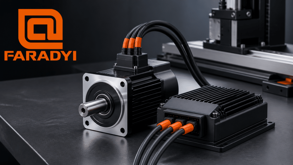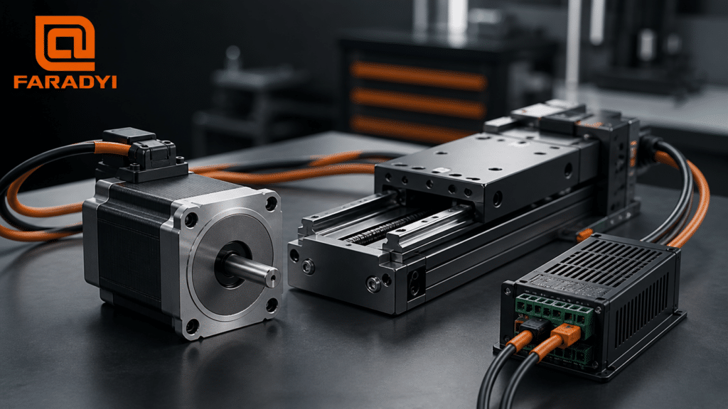
Brushless DC motor torque is determined primarily by the motor’s torque constant and the phase current supplied by the controller. More current can produce more torque within the motor’s linear operating region, but current also raises winding losses and temperature. The practical goal is therefore not simply to “increase stall torque.” It is to deliver the required continuous and peak torque at the target speed, for the required duty cycle, without exceeding the motor, controller, connector, gearbox, or thermal limits.
Quick answer: To increase usable BLDC torque, first confirm the current limit and current measurement, improve commutation or field-oriented control, reduce avoidable mechanical losses, and improve the thermal path. If the application still needs more torque, use suitable gear reduction or select a motor with a higher torque constant, larger active volume, or greater continuous thermal capacity. Never raise current or voltage beyond documented motor and drive limits.
Safety note: A stalled motor has zero shaft speed and therefore produces zero mechanical output power, even though it may draw high current and create substantial heat. Do not perform a locked-rotor test unless the motor manufacturer’s procedure, current limit, temperature monitoring, fixture, and maximum test duration are known.
What Determines Brushless DC Motor Torque?
In the normal unsaturated operating region, electromagnetic torque can be approximated as:
Torque ≈ torque constant (Kt) × torque-producing current
The simple relationship is useful, but it must be applied with the same current convention used in the motor datasheet and controller. Peak versus RMS current, phase versus line current, and trapezoidal versus sinusoidal commutation can change the numerical comparison. Winding temperature, magnetic saturation, commutation angle, rotor position, and mechanical friction also affect measured shaft torque.
Torque constant and winding choice
A higher Kt produces more torque per ampere, but winding changes are not a free performance gain. More turns generally increase torque constant and reduce speed constant, while also changing resistance, inductance, current response, and voltage requirements. Compare candidate windings at the required operating point—not from Kt alone.
Current, copper loss, and temperature
Current creates torque, but winding copper loss rises approximately with current squared (I²R). Doubling current can therefore create roughly four times the resistive loss at the same winding resistance. Resistance also increases as copper heats, so voltage-controlled systems may produce less current and torque as the winding temperature rises. Thermal limits often determine continuous torque before the magnetic or mechanical limit is reached.
Speed and available bus voltage
At higher speed, back electromotive force (back EMF) consumes more of the available bus voltage. The controller then has less voltage headroom to force the commanded current through winding resistance and inductance. A suitable bus voltage can help maintain torque at speed, but at zero speed an adequately regulating current controller—not voltage alone—sets torque.
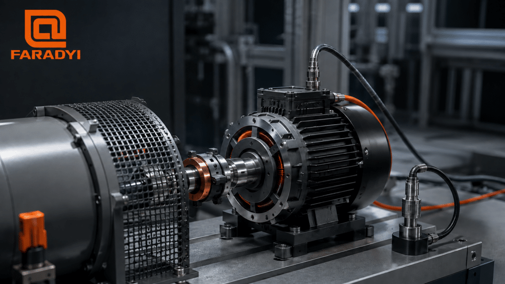
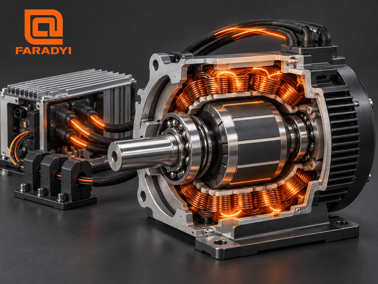 BLDC torque comes from controlled winding current, while the motor housing and mounting path must remove the resulting heat.
Stall Torque vs. Peak and Continuous Torque
These torque values are not interchangeable. When comparing motors, check the test conditions and duration behind each rating.
On a phone, swipe horizontally to view the complete table.
| Torque term | What it means | Primary limit | How to use it |
|---|---|---|---|
| Continuous torque | Torque the motor can deliver without exceeding its stated temperature limit under specified cooling and ambient conditions. | Thermal path, ambient temperature, winding limit, drive current | Size the motor for steady operation and long duty cycles. |
| Peak torque | Short-duration torque available within specified current, temperature, magnetic, and mechanical limits. | Peak current, saturation, demagnetization risk, shaft and drive limits | Check acceleration, shock load, and intermittent overload events. |
| Stall torque | Torque at zero shaft speed under defined electrical and thermal conditions. | Rapid I²R heating, current limit, local hot spots | Use only with the stated test method and allowable duration; do not assume continuous operation. |
| Gearbox output torque | Motor torque multiplied by ratio and gearbox efficiency. | Gear rating, efficiency, backlash, bearing and output-shaft capacity | Increase load-side torque when lower output speed is acceptable. |
Seven Safe Ways to Increase Usable BLDC Torque
1. Verify the controller’s current limits
Confirm the controller’s continuous phase-current limit, peak phase-current limit, peak duration, switching frequency, and cooling condition. Also confirm whether its displayed current is DC-bus, phase peak, or phase RMS current. A mismatch here can make a correctly sized motor appear weak or can unintentionally overheat it.
2. Improve commutation and rotor-position accuracy
Incorrect Hall-sensor order, encoder offset, phase order, or commutation timing reduces torque per ampere and can create extra heat. For servo applications, correctly tuned field-oriented control can align the torque-producing current with rotor flux and provide smoother low-speed torque. Always follow the drive manufacturer’s identification and tuning procedure.
3. Improve heat transfer for higher continuous torque
Use the mounting surface, housing, thermal interface, airflow, or liquid cooling specified for the motor. Monitor winding temperature when possible; housing temperature can lag behind internal hot spots. Better cooling may raise continuous current capability, but it does not authorize exceeding peak current, magnet temperature, insulation, bearing, or shaft limits.
4. Provide adequate voltage headroom at the required speed
If torque falls at higher speed even though temperature is acceptable, the drive may be voltage-limited by back EMF. Select a compatible bus voltage, winding, and controller so commanded current remains achievable at the required speed. Respect maximum motor speed, controller voltage, regenerative voltage, and insulation limits.
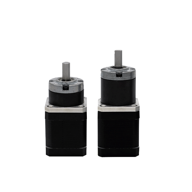
5. Add suitable gear reduction
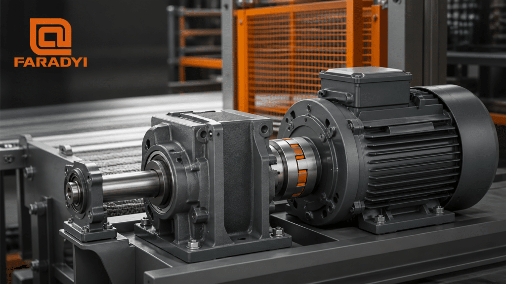
A gearbox can multiply torque at the load while reducing output speed. Estimate output torque as motor torque × ratio × gearbox efficiency, then verify the gearbox’s continuous, peak, radial-load, axial-load, and life ratings. Include backlash and reflected inertia when positioning performance matters.
6. Select a more suitable motor or winding
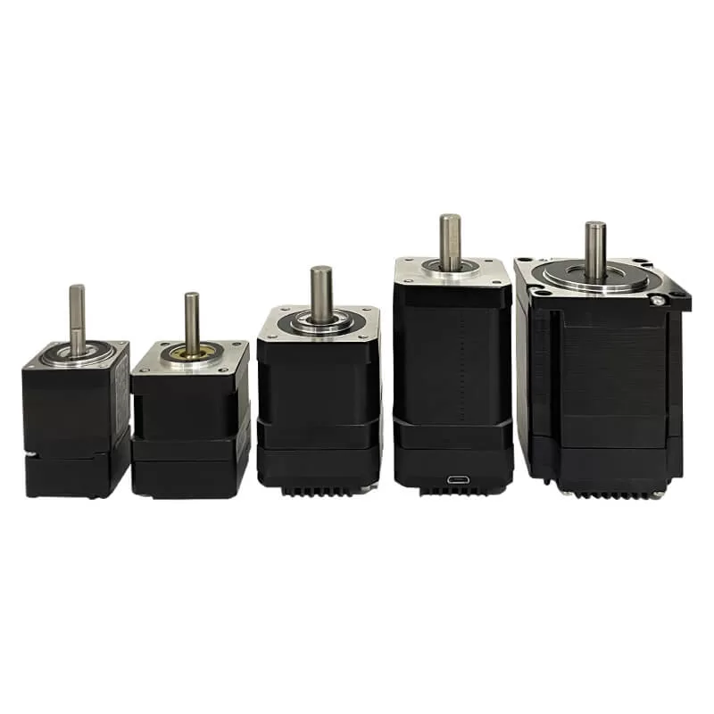
When the present motor is already at its electrical or thermal limit, choose a BLDC motor with more active copper and magnetic volume, a higher continuous torque rating, or a winding matched to the available voltage and speed. Faradyi’s brushless DC motor range can be used as a starting point for comparing form factors and application options; final selection should be confirmed against a model-specific datasheet and operating point.
7. Reduce avoidable drivetrain losses
Check bearing preload, seal drag, shaft alignment, coupling misalignment, brake release, belt tension, gearbox condition, and load mechanism friction. Removing parasitic torque does not increase electromagnetic motor torque, but it increases the torque available to the load and can reduce current and heat.
Why “Just Increase the Voltage” Can Be Misleading
With a simple voltage-driven motor, higher applied voltage at zero speed can force more current through the winding resistance and produce more torque—but it can also exceed current and temperature limits almost immediately. In a properly current-regulated BLDC servo system, the current command and limits determine low-speed torque. Raising the bus voltage above what is needed for current regulation does not automatically raise torque.
Voltage becomes especially relevant as speed and back EMF increase. The correct design question is: Does the controller have enough voltage headroom to maintain the required phase current at the target speed? That is more useful—and safer—than treating voltage as a universal torque adjustment.
Troubleshooting Low Brushless DC Motor Torque
- Measure speed, phase current, bus voltage, and temperature together. A torque complaint cannot be diagnosed from voltage alone.
- Compare the operating point with the motor curve. Check continuous torque, peak torque, rated speed, duty cycle, and cooling conditions.
- Confirm controller conventions. Verify phase current versus bus current and RMS versus peak values.
- Check commutation. Validate phase order, Hall states, encoder direction, electrical angle, and FOC identification.
- Inspect the mechanical load. Look for binding, misalignment, excess preload, gearbox damage, or an unreleased brake.
- Review thermal behavior over time. Torque that starts strong and then falls may indicate thermal limiting, rising winding resistance, or controller derating.
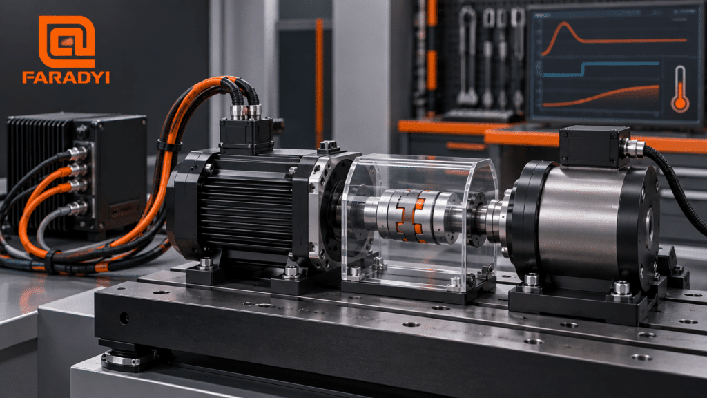
- Use controlled test equipment. Verify torque on a guarded dynamometer or calibrated torque transducer rather than relying on an uncontrolled locked-shaft test.
How to Select a BLDC Motor for a High-Torque Application
Start from the load profile, not a single stall-torque number. Define the required load torque and speed for each part of the motion cycle, calculate RMS torque for thermal sizing, and separately verify peak torque and acceleration. Then check motor speed, drive current, voltage headroom, thermal path, inertia, mechanical interface, feedback, and environmental requirements.
For a useful engineering quotation, provide:
- DC bus or supply voltage and controller information
- Required loaded speed or speed range
- Continuous torque, peak torque, peak duration, and duty cycle
- Ambient temperature, airflow, mounting surface, and enclosure details
- Motor diameter, length, mass, shaft, and mounting constraints
- Feedback type, positioning accuracy, brake, and controller requirements
- Gear ratio, backlash, radial or axial loads, and load inertia if geared
- Ingress protection, noise, life, certification, and expected quantity
Need a BLDC motor matched to your torque-speed cycle?
Share your voltage, loaded speed, continuous and peak torque, duty cycle, dimensions, cooling conditions, feedback, and annual quantity with Faradyi Motor. The engineering team can help review the operating point before you request a final configuration.
Frequently Asked Questions
What is the relationship between BLDC motor torque and current?
Within the motor’s normal unsaturated range, torque is approximately proportional to torque-producing phase current: T ≈ Kt × I. Use the motor manufacturer’s current convention and torque constant, then account for friction, commutation, temperature, and controller limits.
Does increasing voltage increase brushless DC motor torque?
Not automatically. Torque follows current. More bus voltage can help a controller build or maintain current—especially at higher speed—but the controller should limit current to safe motor and drive values. At zero speed, extra voltage without current control mainly increases overheating risk.
Can a BLDC motor hold stall torque continuously?
Only if the manufacturer explicitly specifies continuous stall torque under defined current, ambient, mounting, and cooling conditions. Many published stall or peak values are short-duration limits. A stationary rotor can also concentrate heat in particular windings or drive devices.
Does a gearbox increase motor torque?
A gearbox increases torque at its output while reducing output speed, after accounting for efficiency. It does not increase the motor’s own shaft torque or create additional power. Both the motor operating point and gearbox ratings must remain within limits.
Why does BLDC torque decrease after the motor heats up?
Copper winding resistance rises with temperature, which can reduce current in a voltage-limited system. The controller may also derate current, and magnet flux can decrease as temperature rises. Measuring current and winding temperature helps distinguish these effects.
How should brushless DC motor torque be tested?
Use a guarded dynamometer or calibrated torque transducer with logged speed, phase current, bus voltage, and temperature. Test at defined operating points and durations. A locked-rotor test should only be performed under a documented procedure with fast current limiting and temperature protection.
Conclusion
Increasing brushless DC motor torque safely requires a system-level approach. Current and torque constant set the basic electromagnetic relationship, while commutation, voltage headroom, cooling, duty cycle, saturation, and drivetrain limits determine how much torque is actually usable. Verify the operating point first; then improve control and heat transfer, add appropriate gearing, or select a better-matched motor. This produces a more reliable result than raising voltage or current without a verified thermal and mechanical margin.
Technical References
- Texas Instruments, “A Basic Guide to Motor Control Using a C2000 Real-Time Microcontroller Unit” — current sensing and closed-loop torque control.
- Portescap, “Physical Parameters Affecting Stall Torque of a Brushless DC Motor” — torque constant, stall current, resistance, friction, and temperature effects.
- Microchip Technology, AN885: “Brushless DC (BLDC) Motor Fundamentals” — BLDC construction, commutation, and motor parameters.