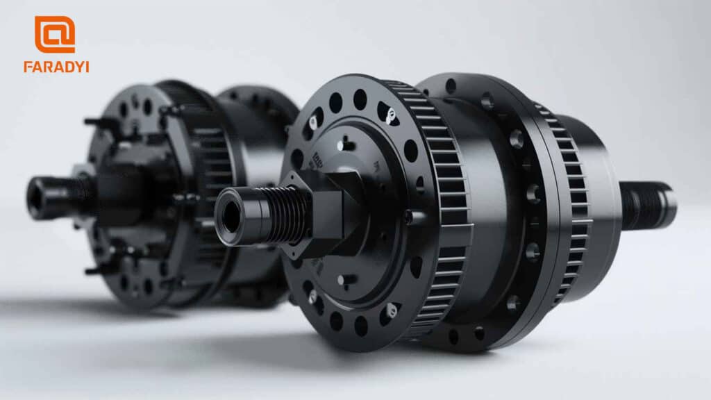
Placing the Hall sensors of a brushless DC motor opposite the magnetic wheel formed by the shaft or rotor extension can detect the rotor’s position. However, this only provides enough commutation signals, which for a three-phase brushless motor means six signals per electrical cycle. These fewer discrete pulses are inadequate for high-performance applications. Optical encoders and rotary transformers can offer high-resolution rotor position signals, but they are relatively expensive and require significant installation preparation. Due to cost and manufacturing burdens, they need to be omitted in large-scale applications. Many methods can estimate commutation signals, summarized briefly below:
(1) Estimation Using Brushless DC Motor Model:
By utilizing external current and voltage along with motor parameters such as resistance, inductance, and mutual inductance, induced electromotive force can be obtained from the model of a brushless DC motor. The advantage of this method is the extraction of isolated signals since current and voltage inputs are inherently isolated signals. Variations in the DC bus voltage can be estimated from the parameters of the DC bus filter and DC bus current. Sensitivity of parameters, particularly stator resistance, may introduce errors in the estimation of induced electromotive force, leading to inaccurate commutation signals to the inverter.
(2) Induced Electromotive Force from Sensing Coils:
Installing sensing coils in a brushless DC motor is cost-effective for obtaining induced back electromotive force signals. The advantage lies in relatively complete signals, insensitivity to parameters, and electrical isolation. However, drawbacks include manufacturing processes and additional wiring from the brushless DC motor. For instance, it’s unsuitable for driving refrigerator compressor motors due to sealing requirements.
(3) Utilizing De-energized Phases to Obtain Back EMF:
One common method for obtaining position information is to monitor the induced back electromotive force of the motor phase winding when the phase winding is de-energized. Note that at any given time, only two phases of the brushless DC motor are conducting, leaving one phase de-energized for 3.33% of the time. During this period, induced back electromotive force appears in the motor’s windings, which can be detected. The polarity of the induced back electromotive force determines the appropriate polarity of the current injected into the brushless DC motor. To avoid waiting for the induced back electromotive force to reach a steady region to energize one phase of the motor, a special value is obtained from the induced back electromotive force, corresponding to 30° away from the zero-crossing moment. The output of the integrator corresponds to 30° away from the positive zero-crossing, termed as a threshold used for energizing one phase.
Assuming a trapezoidal waveform of the induced back electromotive force, when the rotor electrical speed is Wb, its peak is EP. The slope of the rising portion of the induced back electromotive force at any speed can be given by the ratio of the peak voltage at that speed to the time interval corresponding to 30° of electrical angle.
Although sensor output voltages differ, it can be correspondingly demonstrated that this algorithm is also applicable to brushless motors with sinusoidal back electromotive force. Note that the sensor output voltage is constant and independent of the brushless motor’s parameters, with its magnitude equal at any speed. The only possible disadvantage to the sensor output voltage is due to the temperature characteristics of the rotor permanent magnet, which decreases the rotor magnetic flux, resulting in a decrease in the peak value of the induced back electromotive force. This may introduce errors such that energizing may not occur exactly as needed at 30° away from the zero-crossing electrical angle. Without employing additional calibration measures, brushless DC motors may not be optimally utilized.
(4) Third Harmonic of Back EMF:
An alternative method is to detect the 3rd harmonic of the induced back electromotive force within the motor windings and use them to generate control signals. A three-phase star-connected four-wire system allows the collection of the 3rd harmonic of the induced back electromotive force and can be measured inexpensively using four resistors.
(5) AI-Based Control Methods:
Intelligent controllers such as neural networks or fuzzy controllers can extract rotor position or commutation position from variables of the brushless DC motor such as current and magnetic flux. They merely extract feedback information from variables potentially containing rotor position information or commutation conditions. These technologies are adaptive, allowing continuous optimization through self-learning over time. With the increasing speed of current processors, programming controllers for practical applications becomes more feasible. The major drawback of these controllers is that neural network controllers require pre-learning before operation. They can provide offline self-learning functionality.
All methods relying on induced back electromotive force have the disadvantage that position information cannot be obtained when stopped since there is no induced back electromotive force when the speed is zero. Even at very low speeds, induced back electromotive force may not be easily detected. Therefore, to successfully start a brushless DC motor to a certain speed and reliably generate position information at this speed using induced back electromotive force methods, a method for generating control signals at zero speed and nearby must be included. Thus, a startup process is required when a brushless DC motor is stationary. This process can consist of two steps, detailed below:
Step 1: Energize one phase or two phases, and the rotor may align with a pre-determined rotor position. This way, the initial position is known, and correct startup control signals can be generated. Until the rotor starts moving at lower speeds, the induced back electromotive force is very low, and it cannot be used to generate commutation pulses until the rotor reaches a certain speed, requiring the second step to complete the startup process.
Step 2: Once the rotor starts moving, the stator phase winding will be energized with a slowly varying frequency to keep the stator current constant. The rate of frequency change is kept low to maintain synchronicity, and if the load is known, it can be controlled appropriately. If unknown, the stator’s frequency will be repeatedly experimented with until it reaches a minimum speed at which the amplitude of the induced back electromotive force is sufficient for control. This constitutes the second step of the startup process. The problem with this method is its lack of precision, as some jitter and vibration can be felt during the startup process, which may not be meaningful in many applications. In many cases, the first step can be skipped, and only the second step is used to start the brushless DC motor.
Microcontroller Solutions:
There are many microcontroller solutions available in the market for controlling brushless DC motors, including strategies for sensor and sensorless operation, including startup. They are highly popular in the low-voltage range of 12-48V, covering a wide range of applications. When considering brushless motor drives for high-voltage ranges, caution must be exercised as switch noise becomes significant and robust control methods are required in such environments. In the high-voltage range, conventional controller products are mainly controlled by digital signals or other forms of microprocessor control.
Utilizing pole saliency for permanent magnet synchronous motors, employing signal injection to find inductance is another technique for finding rotor position, which needs to be discussed in the application of brushless DC motors. It doesn’t offer much help for brushless DC motors with no clear difference between surface-mounted and interior permanent magnet motors. Note that the signal

