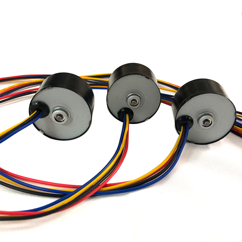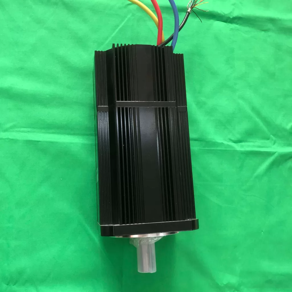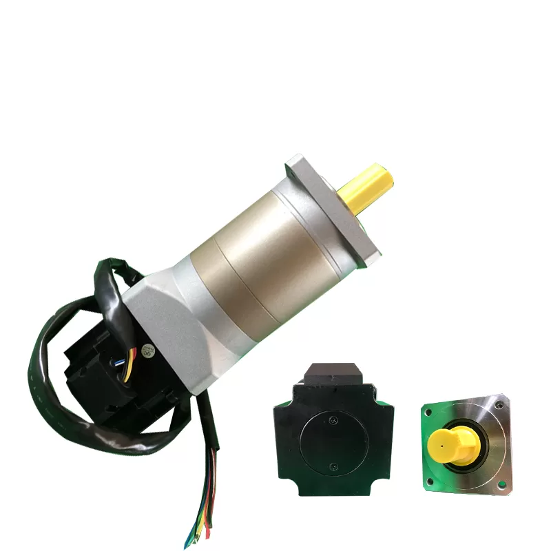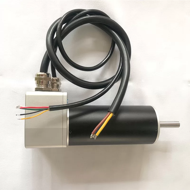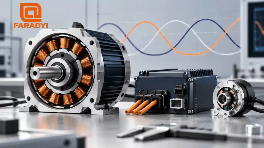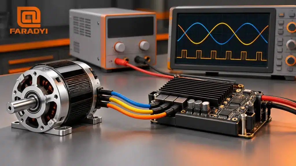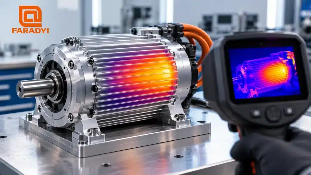
High-power BLDC motor overheating usually means the application is generating more heat than the motor can safely dissipate under its actual operating conditions. The cause may be excessive torque current, repeated acceleration, inadequate cooling, poor thermal mounting, or a motor-drive mismatch. A high power rating alone does not establish the allowable continuous load.
Quick answer: Check the motor’s loaded speed, continuous and peak torque, phase current, duty cycle, ambient temperature, mounting, and cooling against the exact datasheet. High-power BLDC motors can run continuously when rated for that duty and installed under the specified conditions. Housing temperature alone cannot establish winding temperature.
Why a high-power motor can run hot
Motor output power and motor heat are different quantities. Mechanical output is torque multiplied by angular speed; heat comes from losses. At low speed, a motor can produce little output power while carrying substantial current to maintain torque.
Winding loss follows the sum of the phase I²R losses. At the same resistance, doubling current produces four times the copper loss. Core and rotor losses also depend on magnetic variation, speed, and drive waveforms. Bearings, seals, and load friction add mechanical losses. The controller generates its own heat, which can further warm a shared enclosure.
This is why selecting only by advertised watts or peak torque can fail. The continuous operating point and the thermal installation matter just as much.
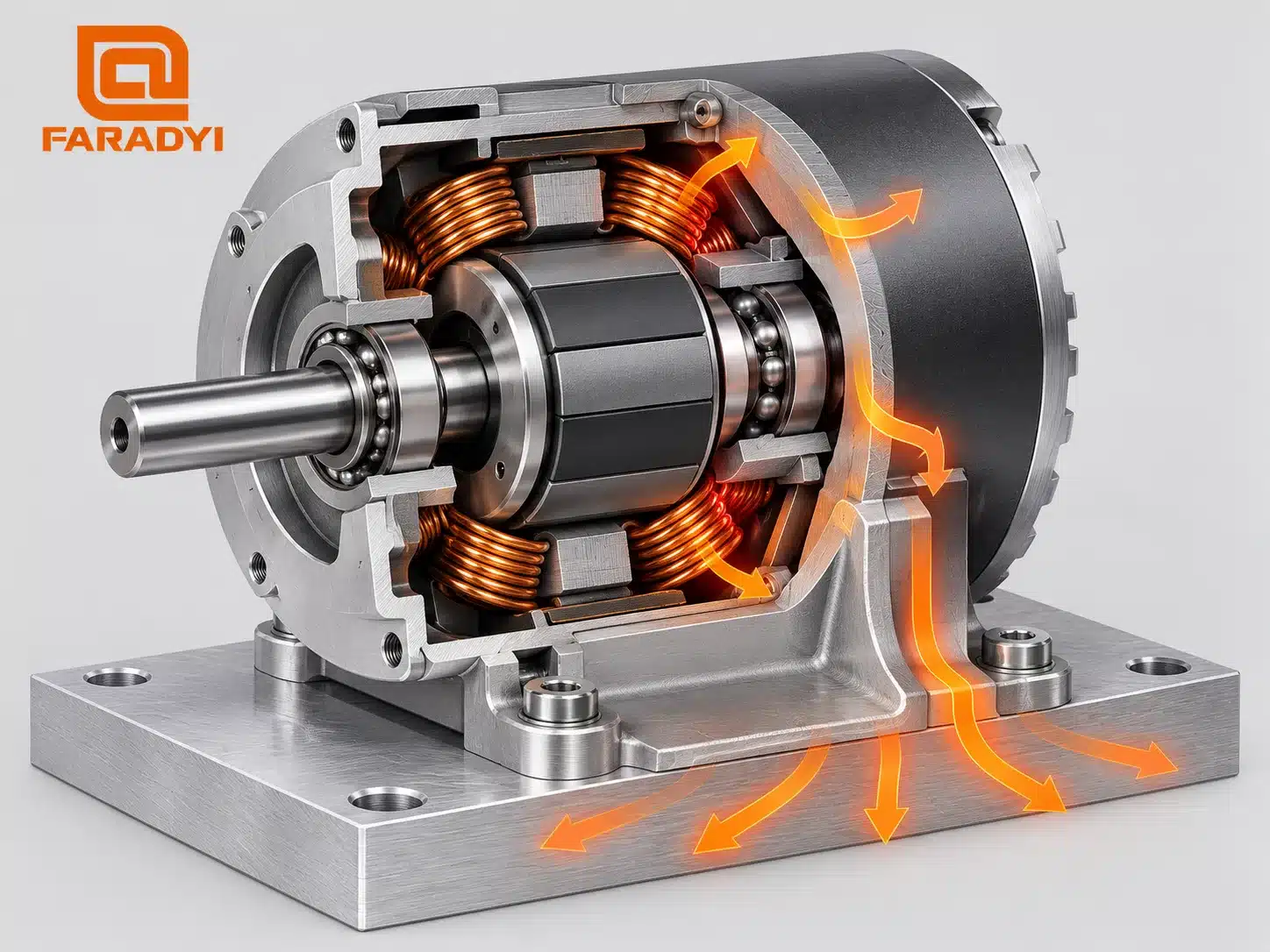
Six checks for high-power BLDC motor overheating
1. Compare the real load with the continuous rating
Record torque and speed during steady running, acceleration, reversal, and holding. A peak rating permits a limited event under stated conditions; it is not a continuous-duty rating. For a repeating load cycle, RMS current or torque can help assess copper heating, but it does not capture every speed-dependent loss or replace a thermal test.
If the machine has recently changed, review belt tension, process load, gearbox drag, alignment, and shaft loads. Increasing the current limit can hide a mechanical problem while making temperature rise worse.
2. Account for starts, stops, and holding torque
Frequent starts and reversals increase time spent at high current. A shorter cycle may therefore raise temperature even if normal running speed is unchanged. Use a ramp that meets the process requirement without demanding unnecessary peak torque.
A stopped servo axis may still carry current to hold position. Reduce holding demand only when the machine remains safe and stable. Holding current, dynamic braking, and a mechanical holding brake are different functions; a simple “stop current” adjustment is not a universal solution. Suspended or back-drivable loads require an appropriate engineered holding strategy.
3. Verify the cooling path and mounting
Check whether the published rating assumes free convection, forced airflow, a metal mounting surface, or another cooling arrangement. A compact motor bolted to an effective heat-spreading plate may behave very differently from the same motor enclosed behind insulating material.
Inspect blocked fins, dust, failed fans, recirculating hot air, and nearby heat sources. Improve the specified thermal path rather than adding a fan without checking where the heat can actually leave the assembly.
4. Include ambient temperature and enclosure heat
Higher ambient temperature leaves less temperature rise available before a component reaches its limit. Measure near the motor under normal enclosure conditions, not only at a distant room thermometer. Review the manufacturer’s derating guidance when the installation differs from its rating conditions.
5. Check controller settings and current quality
Incorrect phase mapping, feedback alignment, motor parameters, or overly aggressive tuning can produce excess current. Low-inductance motors can also experience substantial PWM current ripple. Average DC supply current is not interchangeable with RMS phase current, so use the drive’s definitions when comparing measurements with ratings.
Review PWM frequency and any current filtering with the motor and drive suppliers. Raising switching frequency can reduce current ripple in some combinations, but it can increase inverter switching loss. A controller change must be validated as a complete system.
6. Inspect bearings and electrical connections
A bearing-end hotspot may indicate friction, alignment, or shaft-load trouble. A hot connector may indicate contact resistance rather than a winding problem. Isolate power before checking connectors and mechanical parts; live measurements and rotating-equipment diagnosis belong to qualified personnel.
Match the symptom to the next measurement
| Observed pattern | Possible cause | Useful next check |
|---|---|---|
| Hot during slow, heavily loaded motion | High torque current; insufficient cooling for that duty | RMS phase current, torque demand, cooling specification |
| Temperature rises after a cycle-time reduction | More acceleration or holding current per minute | Complete current-versus-time profile and thermal trend |
| Hot even with little external load | Speed-related losses, ripple, miscommutation, or friction | No-load current at the specified speed and drive settings |
| One bearing end or connector is much hotter | Localized mechanical or connection loss | Alignment, shaft loads, bearing condition, contacts |
| Acceptable on a bench, hot inside the machine | Changed ambient, airflow, or mounting heat transfer | Enclosure air temperature and actual heat path |
On a phone, swipe the table horizontally.
How hot is too hot?
There is no single temperature limit for every high-power BLDC motor. Winding insulation, magnets, bearings, lubricant, sensors, and electronics can have different limits. The applicable specification also identifies the measurement location and operating conditions.
A thermal camera is useful for finding patterns, but shiny metal, emissivity settings, and viewing angle affect surface readings. An internal winding sensor provides different information from a housing measurement, and the housing may respond more slowly. Do not judge an allowable operating temperature by touch.
Smoke, burning odor, damaged insulation, rapid unexplained temperature rise, or repeated protection trips call for shutdown and qualified inspection. Do not bypass protection to complete a thermal test.
Validate the solution under the actual duty
- Establish a baseline: motor and drive models, supply, load, current, speed, cycle, ambient, cooling, and temperature-sensor location.
- Correct the identified cause: mechanical drag, incorrect settings, excessive duty, or an inadequate cooling path.
- Repeat a controlled test using the expected load and enclosure conditions. Observe the thermal trend long enough to assess the intended duty.
- Confirm margin against every relevant component limit and validate fault handling. Recheck after changes to gearing, controller, cooling, or production speed.
For a broader explanation of loss sources, see why electric motors get hot. If heating occurs mainly during acceleration, our BLDC startup guide explains the control tradeoffs. Feedback and current regulation are covered in brushless motor vector control.
Frequently asked questions
Can a high-power BLDC motor operate continuously?
Yes, when its continuous rating covers the required operating point under the actual installation conditions. Power class alone does not determine duty capability.
Will a larger controller keep the motor cooler?
Not necessarily. A controller with more current capacity can still overheat the motor if limits, feedback, or tuning are wrong. Match the drive to the motor’s requirements.
Should I reduce current whenever the motor is hot?
Reducing unnecessary current can reduce winding loss, but the motor must still produce the required torque safely. Diagnose the load and control settings before changing limits, especially on a holding axis.
Select for thermal duty, not peak watts
Preventing high-power BLDC motor overheating begins with a motor-drive combination sized for its real operating cycle. Browse Faradyi’s brushless DC motors そして send the engineering team your supply voltage, continuous and peak torque, loaded speed, duty cycle, current records, controller details, ambient temperature, mounting, cooling, space limits, and quantity.
Technical references: maxon: Motor Heating and PWM Current Ripple; FAULHABER: Motor Thermal and Application Support.