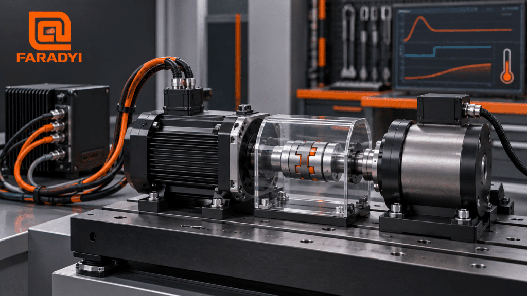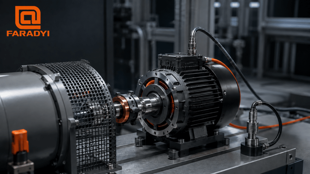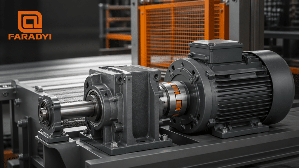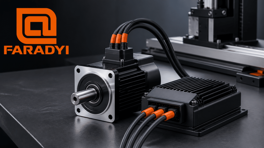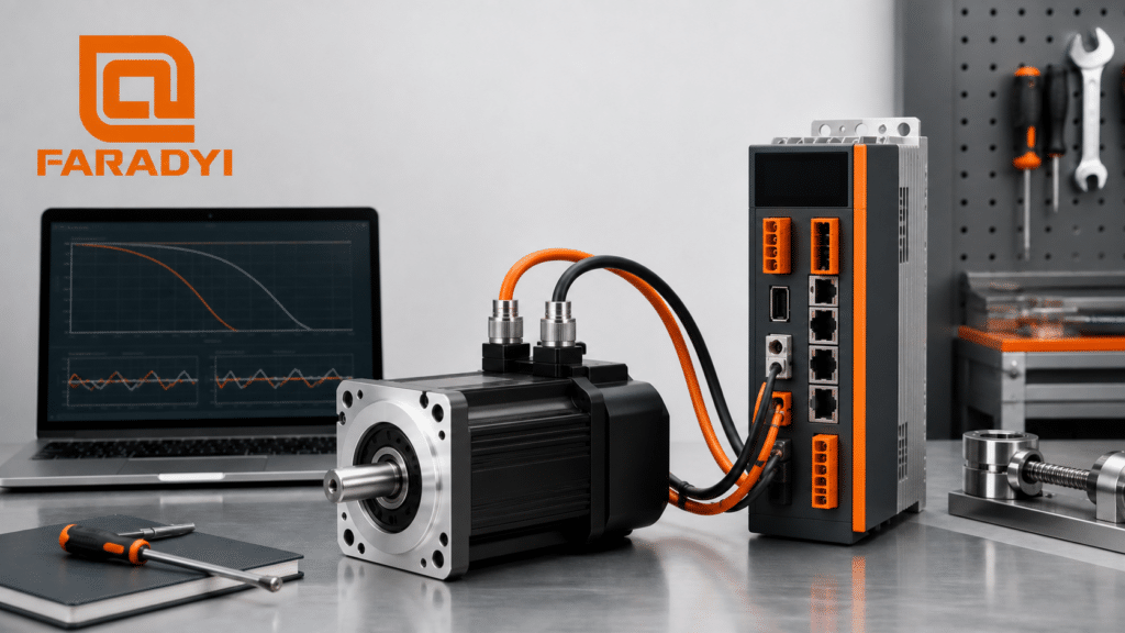
Servo motor technical specifications describe how much continuous and peak torque a motor can produce, the speed range where that torque is available, its electrical requirements, rotor inertia, feedback device, mechanical dimensions, environmental limits, and compatibility with a servo drive. These values must be evaluated as a system—not as isolated numbers—because the motor, drive, feedback, transmission, load, control loop, and duty cycle all affect real machine performance.
What Are Servo Motor Technical Specifications?
A servo motor specification sheet defines the operating boundaries and physical characteristics of a particular motor model under stated conditions. Typical values include rated torque, peak torque, rated speed, maximum speed, output power, rated current, torque constant, voltage constant, winding resistance and inductance, rotor inertia, encoder type, thermal class, protection rating, mass, shaft dimensions, and allowable loads.
A servo system adds more specifications: input power, supported feedback interfaces, control modes, loop response, command interfaces, communications, protective functions, braking provisions, tuning tools, and safety functions. A motor datasheet cannot by itself prove the accuracy, response, or safety of the complete axis.
Motor specification versus system performance
Encoder resolution is a motor or feedback-device characteristic. Positioning accuracy and repeatability are complete-axis results influenced by encoder error, coupling compliance, gearbox backlash, ball-screw lead error, bearing play, structural deflection, thermal growth, controller interpolation, tuning, and measurement method. Similarly, a high peak-torque rating is useful only when the drive can supply the necessary current and the permitted peak duration matches the motion cycle.
How a Servo Control System Works
An industrial servo system normally contains a motion controller, servo drive, motor, feedback device, power and feedback cables, and the driven mechanical axis. The controller sends a position, velocity, or torque command. The drive regulates motor current and compares the command with feedback. It continuously corrects the error to achieve the requested motion.
Position control commonly uses nested loops: an outer position loop commands velocity, the velocity loop commands torque-producing current, and the inner current loop regulates motor torque. The exact architecture and which loops run in the controller or drive depend on the product and application.
Most modern industrial servomotors are based on brushless permanent-magnet motor technology because electronic commutation supports efficient, responsive closed-loop operation. However, a brushless motor becomes part of a servo system only when it is paired with appropriate feedback, drive electronics, and control.
Key Servo Motor Technical Specifications
| 仕様 | Typical unit | What it means | Selection question |
|---|---|---|---|
| 定格トルク | N·m, oz-in, lb-in | Torque available continuously under stated thermal conditions | Is the cycle’s RMS torque inside the continuous operating region? |
| Peak torque | N·m | Short-duration torque subject to time, current, speed, and thermal limits | Can it cover acceleration and disturbance peaks for the required duration? |
| Rated / maximum speed | rpm, rad/s | Continuous base point and upper permitted rotational speed | Is required torque available at the actual operating speed? |
| 定格出力 | W, kW, hp | Mechanical output near a specified rated operating point | Does the torque-speed curve—not only power—fit the cycle? |
| ローター慣性 | kg·m², oz-in-s² | Resistance of the rotor to angular acceleration | Is reflected load inertia acceptable for stable, responsive control? |
| トルク定数 | N·m/A | Torque produced per specified current convention | Are RMS/peak and phase/line current conventions consistent? |
| Back-EMF constant | V/krpm, V/(rad/s) | Generated voltage relative to speed under a defined convention | Can the drive bus support the required speed under load? |
| Encoder resolution | bits, counts/rev, pulses/rev | Number of distinguishable feedback positions under the stated counting method | Does the feedback type and interface match the drive and control goal? |
| Protection / environment | IP code, °C, humidity, altitude | Permitted exposure and operating conditions | Is derating, sealing, cooling, or a different connector needed? |
On a phone, swipe the table horizontally to view every column.
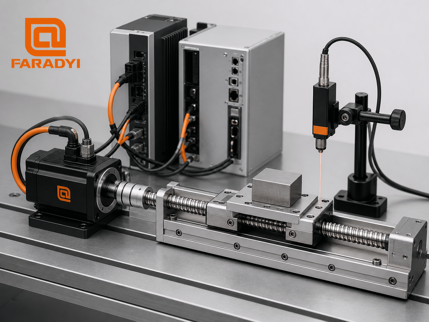
Torque, Speed, and Power: Read the Curve
Rated torque and continuous operation
Rated torque is generally the torque a motor can deliver continuously at defined ambient, mounting, cooling, winding-temperature, and drive conditions. A machine’s time-weighted RMS torque requirement should remain within the continuous zone of the approved motor-drive torque-speed curve. Installation differences can require derating.
Peak torque and acceleration
Peak torque supports acceleration, deceleration, breakaway friction, and short disturbances. It is not a continuous rating. The maximum permitted duration and repetition rate depend on drive current, motor thermal limits, speed, winding temperature, and duty cycle. Use the manufacturer’s time-current or torque-speed limits for the exact motor-drive pairing; do not assume a universal overload multiple.
Speed and voltage margin
Maximum speed is a mechanical and electrical limit, not a promise that peak torque remains available at that speed. As speed rises, back EMF consumes more of the drive’s available voltage, leaving less voltage to force current into the windings. Review continuous and intermittent curves at the intended DC-bus or AC-input voltage.
Power is not enough for sizing
Mechanical power relates torque and angular speed: P = T × ω. Two motors with the same rated power can have very different torque, speed, inertia, and thermal behavior. Choose from the motion profile and torque-speed envelope, then use power as a cross-check.
Rotor Inertia and Load Matching
Rotor inertia affects how quickly the motor can accelerate. The mechanism’s inertia must be reflected through gears, belts, screws, and couplings to the motor shaft. A high load-to-motor inertia ratio can make tuning more sensitive, increase settling time, or demand more acceleration torque. A very large motor may lower that ratio but add cost, mass, rotor inertia, and energy consumption.
There is no universal “correct” inertia ratio. Acceptable values depend on mechanical stiffness, backlash, resonance, bandwidth, transmission ratio, motion profile, and the drive’s tuning capability. Use the drive manufacturer’s sizing guidance and validate the real machine.
Encoder Specifications and Position Feedback
Incremental encoders report changes in position and normally require a reference procedure after power-up. Absolute encoders provide a coded position; single-turn devices identify angular position within one revolution, while multi-turn systems also track revolutions within their stated range and power-loss behavior.
When reviewing feedback, check:
- incremental, absolute single-turn, or absolute multi-turn operation;
- resolution and the vendor’s counting convention;
- accuracy and repeatability, if specified separately;
- electrical interface and protocol compatibility;
- maximum feedback speed and communication cycle;
- battery-backed or batteryless multi-turn behavior;
- cable type, permitted length, shielding, and connector;
- commutation alignment and drive compatibility.
Higher resolution can improve measurement granularity, but it cannot remove gearbox backlash, compliance, thermal drift, or poor tuning. If load-side accuracy is critical, consider whether a secondary linear or rotary feedback device is required at the load.
Electrical and Thermal Specifications
Rated current, peak current, winding resistance, inductance, torque constant, and back-EMF constant help determine compatibility with the drive. Carefully compare definitions: one datasheet may use phase current while another uses line current, and peak values are not interchangeable with RMS values.
Thermal performance depends on copper loss, iron loss, ambient temperature, mounting surface, airflow, enclosure, altitude, cable losses, and motion cycle. Confirm the specified winding or case-temperature limit and how it is monitored. A temperature sensor can help protect the motor, but the drive must support the sensor type and its protective behavior must be configured and validated.
Mechanical and Environmental Specifications
Confirm flange dimensions, pilot diameter, bolt pattern, shaft diameter and length, keyway or flat, allowable radial and axial load, connector direction, cable bend radius, motor mass, and optional brake dimensions. A motor can be electrically suitable but impossible to integrate because its connector interferes with the machine envelope.
Environmental checks include ambient temperature, humidity, altitude, vibration, shock, dust, liquid exposure, corrosive agents, cleanroom or washdown requirements, and hazardous-location constraints. An IP rating applies only under its stated installation conditions and does not automatically establish chemical resistance, washdown suitability, or hazardous-location approval.
Servo Performance Parameters Beyond the Motor Datasheet
| System parameter | Why it matters | Common mistake |
|---|---|---|
| Positioning accuracy | Difference between commanded and measured physical position | Treating encoder resolution as complete-axis accuracy |
| Repeatability | Ability to return to the same position under defined conditions | Ignoring approach direction, load, temperature, and measurement method |
| Settling time | Time for error to enter and remain within a defined band | Quoting response without an error band or test motion |
| Bandwidth | How quickly a tuned loop can respond to commands and disturbances | Assuming maximum gain is always stable or desirable |
| Following error | Difference between command and feedback during motion | Ignoring command profile and feedforward configuration |
| Speed regulation | Change in actual speed with load or supply variation | Using a no-load speed number as loaded stability |
On a phone, swipe the table horizontally to view every column.
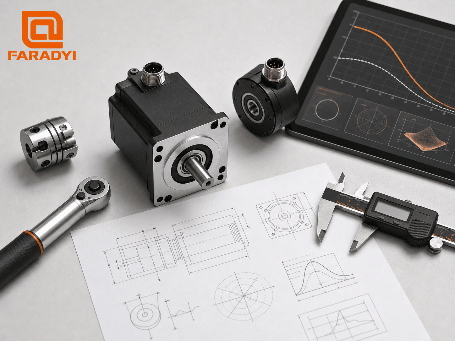
Servo Loop Tuning Parameters
Servo tuning balances response, stability, noise sensitivity, and mechanical stress. Parameter names and units vary by drive, so use the specific manual and commissioning software.
Position-loop gain
Higher position gain can reduce following error and increase apparent stiffness, but excessive gain may excite resonance, create overshoot, or cause oscillation. The stable value depends on mechanics, load inertia, feedback, and inner-loop tuning.
Velocity-loop gain and integral action
Velocity proportional gain affects response to speed error and disturbances. Integral action reduces steady-state speed error, but aggressive settings may decrease stability. Gain should not simply be set “as high as possible”; it should meet a defined response requirement with adequate stability margin.
Feedforward, filters, and resonance suppression
Velocity or acceleration feedforward can reduce tracking error without relying only on feedback gain. Low-pass and notch filters can reduce noise or suppress mechanical resonance, but unnecessary filtering adds phase delay. Measure the machine response and change one parameter group at a time.
Which Standards Apply to Servo Systems?
No single standard covers every servo motor, drive, machine, environment, and U.S. installation. Applicable requirements depend on the product scope, supply voltage, machine type, location, safety functions, end-use certification, and authority having jurisdiction.
- IEC 61800-5-1 addresses electrical, thermal, fire, mechanical, energy, and related hazards for adjustable-speed electrical power drive systems and their elements.
- UL 61800-5-1 is a U.S. safety standard for adjustable-speed electrical power drive systems. UL Solutions published its second edition in 2022.
- IEC 61800-5-2 addresses functional safety requirements for safety-related power drive systems.
- IEC 61800-3 addresses electromagnetic compatibility requirements and test methods for power drive systems.
- NFPA 79, UL 508A, and the National Electrical Code may be relevant to U.S. industrial machinery, control panels, wiring, and installation, depending on the system scope.
- ISO 13849-1 or IEC 62061 may be used in machine-safety control-system design, depending on the chosen methodology and applicable requirements.
A reference to a standard is not evidence that a product is certified or that a complete machine complies. Request the exact certification listing, test report, scope, edition, model number, and installation conditions. Consult a qualified compliance professional and the authority having jurisdiction for the final U.S. application.
How to Select a Servo Motor Step by Step
- Define the motion profile. Record travel, move time, acceleration, deceleration, dwell, direction changes, and cycles per minute.
- Model the mechanics. Include payload, friction, gravity, transmission efficiency, screw lead, gear ratio, coupling, and external forces.
- Calculate torque and speed. Determine continuous RMS torque, peak torque, and maximum motor speed for the full cycle.
- Check the torque-speed envelope. Confirm every operating point against the approved motor-drive curve at the intended supply.
- Reflect load inertia. Evaluate acceleration response, tuning sensitivity, gearing, and resonance.
- Select feedback. Match resolution, absolute/incremental behavior, accuracy, protocol, and cable needs.
- Verify mechanical integration. Check flange, shaft, loads, connectors, brake, mass, and available space.
- Verify the environment. Account for temperature, altitude, vibration, contaminants, enclosure, and cooling.
- Match the drive and controls. Confirm current, voltage, feedback, control mode, network, regenerative energy handling, safety functions, and cables.
- Validate the real axis. Test temperature, following error, settling, repeatability, noise, resonance, and fault behavior under representative loads.
Common Servo Specification Mistakes
- Selecting by watts or horsepower without checking the torque-speed curve
- Using peak torque as a continuous rating
- Ignoring the duration and repetition limits of intermittent operation
- Equating encoder resolution with machine accuracy
- Comparing current or voltage constants that use different conventions
- Ignoring reflected load inertia, compliance, backlash, and resonance
- Assuming an IP rating covers every contaminant or washdown process
- Mixing a motor and drive without confirmed feedback and commutation compatibility
- Claiming standards compliance from a component reference alone
Where Brushless Motors Fit
Brushless DC and permanent-magnet synchronous motor designs are widely used in servo applications, but the intended commutation method, winding, sensor, drive, and operating envelope must match. Faradyi Motor’s brushless motor range provides a starting point for discussing motor requirements. Product suitability should be confirmed from an application-specific datasheet and engineering review.
Information to Provide for a Servo Motor Quote
Clear application data helps avoid both undersizing and unnecessary cost. Include:
- available AC input and DC-bus voltage, if already defined;
- motion profile or speed-versus-time data;
- continuous RMS torque and peak torque, or enough mechanical data to calculate them;
- payload, external force, friction, transmission type, efficiency, and gear ratio;
- reflected load inertia or complete mechanism dimensions and masses;
- accuracy, repeatability, settling-time, and following-error requirements with test conditions;
- encoder type, resolution, absolute/multi-turn needs, and interface;
- flange, shaft, connector, cable, brake, and overall envelope requirements;
- ambient temperature, altitude, vibration, dust, liquid, and duty cycle;
- controller, network, drive, and required safety functions;
- prototype and expected annual quantities.
Discuss Your Brushless Servo Motor Requirements
Send Faradyi Motor your torque-speed profile, voltage, feedback, mechanical envelope, environment, and quantity for an engineering review.
よくある質問
What are the most important servo motor technical specifications?
Start with continuous RMS torque, peak torque, required speed, torque-speed curves, rotor inertia, feedback type, voltage and current, duty cycle, environmental limits, dimensions, and drive compatibility.
What is the difference between rated torque and peak torque?
Rated torque is intended for continuous operation under stated thermal conditions. Peak torque is available only for limited periods and depends on current, speed, temperature, and repetition. Use the exact motor-drive limits.
Does a higher-resolution encoder guarantee better accuracy?
No. Resolution is measurement granularity. Complete-axis accuracy also depends on encoder accuracy, mechanics, backlash, compliance, thermal effects, tuning, and control architecture.
How do I calculate servo motor power?
Mechanical power equals torque multiplied by angular speed. In SI units, P(W) = T(N·m) × ω(rad/s). Servo sizing still requires the complete motion cycle and torque-speed curve.
What is a good load-to-motor inertia ratio?
There is no universal ratio. The acceptable value depends on stiffness, transmission, resonance, backlash, required response, and drive tuning. Follow the drive maker’s guidance and validate the actual axis.
Are brushless DC motors the same as servo motors?
Not automatically. A brushless motor is a motor technology. A servo system combines a suitable motor with feedback, a compatible drive, and closed-loop control to regulate position, speed, or torque.
Which servo standard is required in the United States?
The answer depends on the drive, machine, installation, safety functions, and end use. UL 61800-5-1 may apply to adjustable-speed drive safety, while other machine, panel, electrical, EMC, and functional-safety requirements may also apply. Confirm the scope with qualified compliance professionals and the authority having jurisdiction.
結論
Reliable servo selection comes from interpreting servo motor technical specifications as a connected system. Match continuous and peak torque to the full duty cycle, verify the torque-speed envelope, account for inertia and mechanics, choose compatible feedback and drive electronics, and evaluate environmental and compliance requirements. For an application-specific discussion, review Faradyi Motor’s brushless DC motor options and provide the engineering details needed to qualify the motor rather than selecting from one headline rating.