Learning how to wire a stepper motor starts with three checks: identify which leads belong to each phase, confirm whether the motor has 4, 5, 6, or 8 wires, and use a compatible stepper driver. Do not rely on wire color alone—colors are not universal across motor manufacturers.
For a typical 4-wire bipolar motor, use a multimeter to find the two wires with continuity and connect that pair to one driver phase. Connect the remaining pair to the other phase. Then configure the driver current limit before running the motor. This guide explains that process and the differences for other lead configurations.
How to Wire a Stepper Motor Safely
A stepper motor does not connect to a power supply in the same way as a basic two-wire DC motor. Its windings must be energized in a controlled sequence. A dedicated stepper driver performs that switching, while a motion controller, PLC, or microcontroller normally sends step and direction signals.
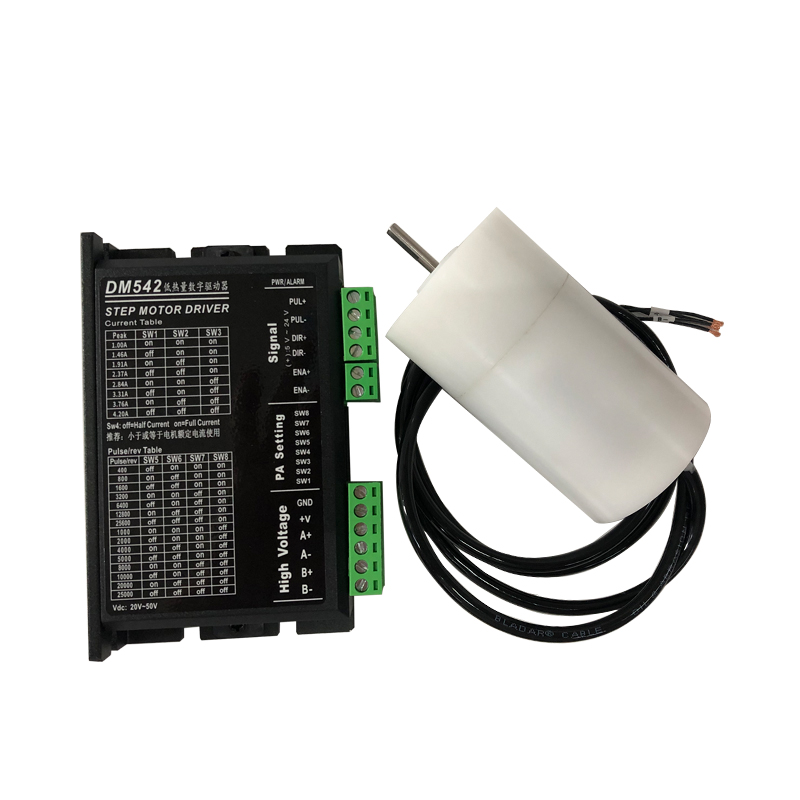
The exact terminals vary by driver. Motor outputs may be marked A+, A−, B+, and B−; A1, A2, B1, and B2; or with another equivalent convention. Always use the diagram supplied with your driver instead of assuming that one vendor’s terminal order applies to another.
Before you begin
- Find the motor datasheet or nameplate information, including phase current, phase resistance, and lead configuration.
- Confirm that the driver supports the motor’s wiring type, current, and intended supply voltage.
- Turn off and isolate the motor power supply.
- Set a multimeter to resistance or continuity mode for lead identification.
- Label each verified phase pair before connecting the driver.
- Insulate every unused lead individually so it cannot short to another wire or the machine frame.
What You Need
- A stepper motor and its datasheet
- A compatible constant-current stepper driver
- A regulated motor power supply within the driver’s rated range
- A controller that provides the driver’s required control signals
- A digital multimeter
- Proper connectors, ferrules or terminals, insulation, and strain relief
Do not power a stepper motor directly from a microcontroller’s GPIO pins. The controller provides low-power logic signals; the stepper driver supplies and regulates winding current.
Understand the Motor, Driver, and Controller
A common motion system has three distinct electrical sections:
- Control: step/direction or other command signals from a controller.
- Drive: a stepper driver that regulates current and commutates the motor phases.
- 力: a motor supply connected to the driver—not directly to the controller’s logic pins.
A bipolar stepper has two phases. The driver reverses current through those windings to move and hold the rotor. A unipolar motor uses center taps so current can be switched through portions of each winding. Lead count is therefore a useful clue, but the datasheet remains the preferred source.
How to Identify Stepper Motor Wires With a Multimeter
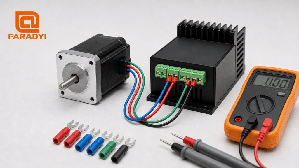
When the datasheet is missing, a resistance test can identify windings without depending on color. Disconnect the motor from all equipment, separate the bare wire ends, and test combinations methodically.
- Set the meter to its lowest practical resistance range or continuity mode.
- Touch the probes together and note the lead resistance if the meter does not compensate automatically.
- Test two motor wires at a time.
- A finite, stable resistance indicates an electrical path through a winding. An open reading indicates wires from different phases.
- Label confirmed wires before moving to the next combination.
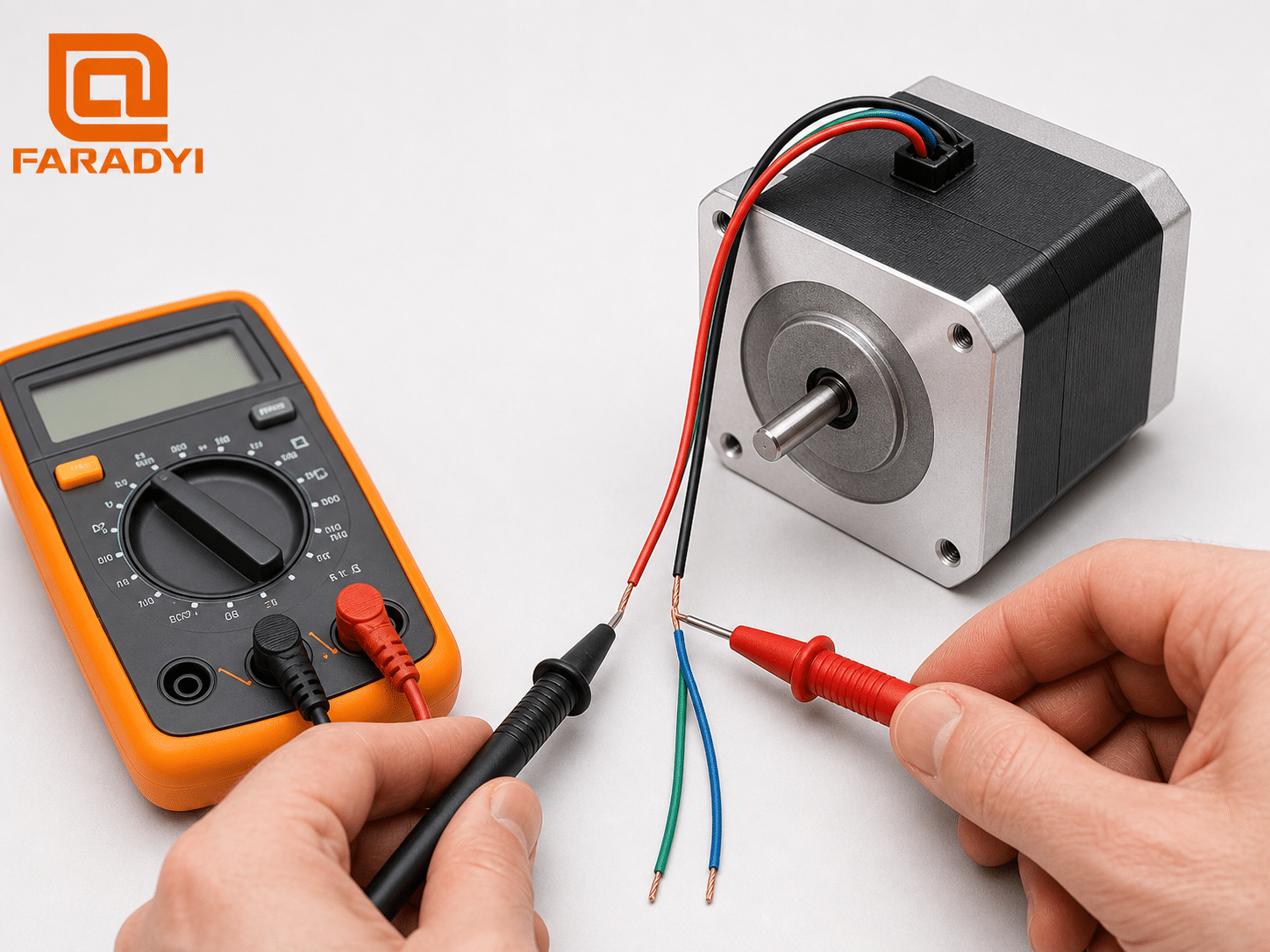
On a 4-wire motor, continuity identifies two independent pairs. A 6-wire motor usually has a center tap for each phase: resistance from one end to the center tap is approximately half the resistance measured from end to end. An 8-wire motor contains four separate half-windings; use its winding diagram to determine polarity before creating series or parallel connections.
How to Wire a 4-Wire Bipolar Stepper Motor
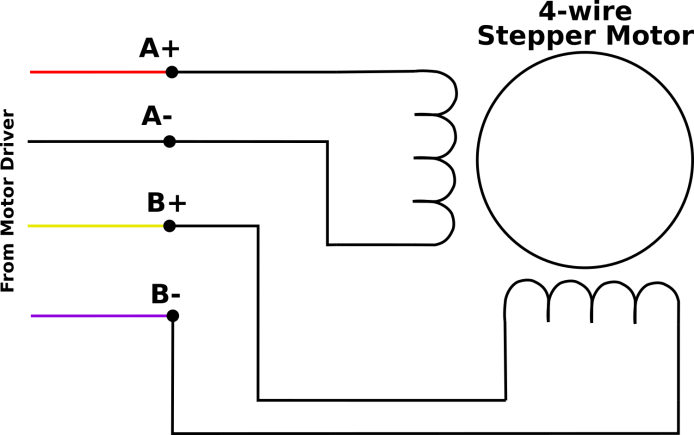
A 4-wire bipolar motor is the most straightforward configuration for a bipolar stepper driver. It has two isolated winding pairs and no accessible center taps.
- Use the datasheet or multimeter to find phase A’s two wires.
- Connect those two wires to the driver’s two phase-A outputs.
- Connect the remaining winding pair to the two phase-B outputs.
- Connect logic, motor power, and grounding/reference wiring as required by the driver manual.
- Set the current limit, restore power, and test at low speed and acceleration.
If the motor only vibrates or locks without rotating, one supposed phase pair may contain a wire from each winding. Power down and verify the pairs again. If rotation is smooth but reversed, change the direction command in software or—while power is off—reverse the two wires of one phase.
How to Wire a 5-Wire Unipolar Stepper Motor
A 5-wire motor usually has two center-tapped windings whose center taps are joined inside the motor. It is designed primarily for a compatible unipolar driver.
The shared internal connection makes a standard 5-wire motor generally unsuitable for direct connection to a typical bipolar chopper driver. Do not guess at modifications or cut into the motor. Use a driver designed for that topology, or select a 4-, 6-, or 8-wire motor when bipolar operation is required.
How to Wire a 6-Wire Stepper Motor
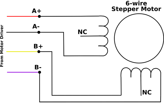
A 6-wire motor has two center-tapped phases. It can often be used with either a unipolar driver or a bipolar driver, depending on how the leads are connected.
Bipolar full-coil connection
Connect the two outer ends of each phase to the corresponding bipolar driver outputs. Leave both center taps disconnected and insulate them separately. This uses the full winding, generally producing more low-speed torque per ampere but higher inductance, which can limit high-speed current rise.
Bipolar half-coil connection
For each phase, connect one outer lead and its center tap, leaving the other outer lead insulated. The lower inductance can improve higher-speed behavior, but the appropriate current setting differs. Use the motor manufacturer’s rating for the selected connection.
Unipolar connection
Connect the two center taps and four winding ends exactly as specified by the unipolar driver documentation. Never assume the common-wire arrangement from color alone.
How to Wire an 8-Wire Stepper Motor
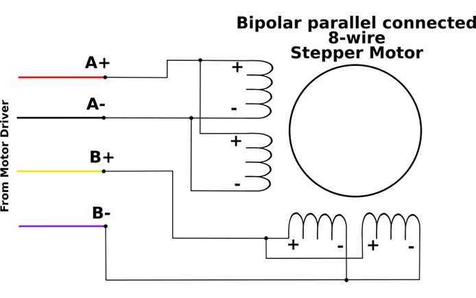
An 8-wire motor exposes both ends of four half-windings. This provides the most connection flexibility, but polarity matters. Identify each half-winding and use the manufacturer’s phase-polarity diagram before joining wires.
Series connection
Connect the two half-windings of each phase in series with additive magnetic polarity, then connect the two completed phases to the driver. Series wiring normally requires less current and has higher inductance. It is often appropriate when low-speed torque and lower driver-current demand matter more than maximum speed.
Parallel connection
Connect matching half-windings in parallel with correct polarity. Parallel wiring normally requires more current and has lower inductance, which can support better torque at higher speed. The driver must be able to supply the parallel current rating.
Incorrectly joining half-windings with opposing polarity can cancel torque or cause erratic behavior. Treat the datasheet winding diagram as mandatory for an 8-wire motor.
Stepper Motor Lead Comparison
| Lead count | Typical construction | Common driver choice | Key wiring note |
|---|---|---|---|
| 4 | Two isolated windings | Bipolar | Connect one coil pair to each driver phase. |
| 5 | Two center-tapped windings with a shared internal common | Unipolar | Usually not directly compatible with a standard bipolar chopper driver. |
| 6 | Two center-tapped windings | Unipolar or bipolar | For bipolar use, choose full-coil or half-coil wiring and insulate unused leads. |
| 8 | Four independent half-windings | 双極性か単極性か | Verify polarity; bipolar phases may be wired in series or parallel. |
On a phone, swipe the table horizontally to see every column.
Connect the Stepper Motor to Its Driver
Once the winding pairs and driver compatibility are confirmed, use this manufacturer-neutral sequence:
- Remove power. Confirm that the driver’s motor supply is off and discharged.
- Verify each phase. Check the datasheet or repeat the resistance test.
- Prepare conductors. Use suitable wire gauge, terminals, ferrules, insulation, and strain relief for the current and environment.
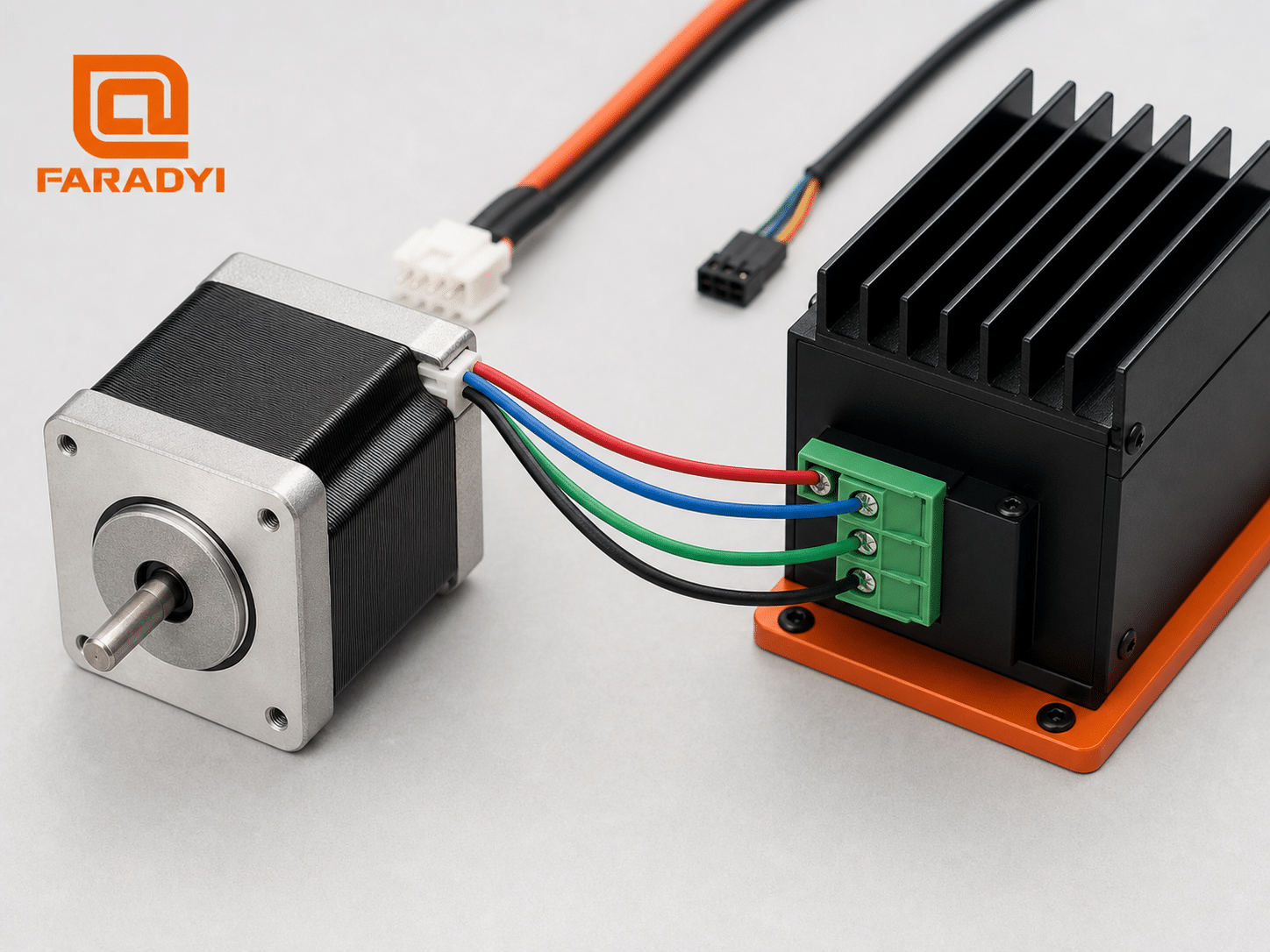
- Connect phase A. Land one complete winding pair on the two outputs assigned to phase A.
- Connect phase B. Land the second winding pair on the two outputs assigned to phase B.
- Connect motor power and logic. Follow the driver’s polarity, grounding, enable, step, and direction requirements. Provide a shared signal reference or differential connections as specified.
- Set the current limit. Use the driver manufacturer’s procedure and the motor’s phase-current rating for the chosen connection.
- Inspect and test. Check for loose strands and shorts, then begin with conservative speed and acceleration.
Set the Driver Current Limit Correctly
The current limit protects the motor and helps it produce predictable torque. Set it from the driver’s documented method, using the motor phase-current specification for the actual series, parallel, full-coil, or half-coil connection.
Do not size or tune a chopper driver by comparing power-supply current directly with motor phase current. They are not the same measurement. Driver formulas may use RMS current, peak current, a reference voltage, DIP-switch settings, or software configuration. Follow the exact driver manual.
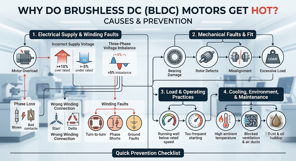
A stepper motor may feel warm while holding position because it can draw current even when stopped. Excessive temperature, odor, discoloration, or repeated protection trips require immediate shutdown and diagnosis. Faradyi’s guide to stepper motor overheating provides additional checks.
Change Stepper Motor Direction
The preferred method is usually to invert the direction setting in the controller or drive configuration. If a wiring change is necessary, switch off and discharge power, then reverse the two conductors of one phase. Reversing both phases preserves the original direction.
Never rearrange motor leads with the driver energized. Also avoid moving a connected motor rapidly by hand; a stepper motor can act as a generator and feed voltage back toward the electronics.
Common Stepper Motor Wiring Problems
| Symptom | Likely causes | What to check |
|---|---|---|
| Vibrates but does not rotate | Incorrect coil pairing, open phase, or wrong 8-wire polarity | Power down; retest winding continuity and compare with the datasheet. |
| Rotates in the wrong direction | Direction convention is reversed | Invert direction in software or reverse one phase with power off. |
| Motor or driver overheats | Current set too high, poor cooling, incorrect connection, or excessive holding current | Verify current method, motor rating, airflow, and idle-current settings. |
| Skips steps or stalls | Acceleration too high, insufficient torque, mechanical binding, inadequate supply, or current too low | Reduce motion demands, inspect the load, and verify the motor/driver sizing. |
| Erratic motion or false steps | Loose terminals, electrical noise, poor grounding/reference, or control-signal problems | Secure connections; separate motor and signal wiring; follow shielding and grounding guidance. |
On a phone, swipe the table horizontally to see every column.
Wiring Practices for Reliable Machines
- Keep motor cables away from low-level sensors and communication wiring.
- Use twisted phase pairs where recommended and maintain each pair consistently through connectors.
- For long cables or electrically noisy equipment, follow the driver maker’s shielding and shield-termination guidance.
- Ground the machine frame and protective earth correctly; do not improvise safety grounding.
- Provide strain relief so cable motion does not transfer force to terminals.
- Document connector pinouts and phase labels for maintenance.
- Do not use color alone as the service record; retain the verified pinout.
Choose a Compatible Stepper Motor and Driver
Correct wiring cannot compensate for an undersized motor, an incompatible driver, or a poorly matched mechanical load. Consider required holding and running torque, speed range, duty cycle, available voltage, phase current, rotor inertia, environmental conditions, connector style, and control interface.
Faradyi Motor supplies ステッピングモーター for industrial motion applications. Share your load, target speed, available voltage, mounting limits, shaft requirements, and estimated annual quantity so the engineering team can recommend a practical motor and driver approach.
Need Help Selecting a Stepper Motor?
Tell Faradyi Motor about your motion profile, power supply, installation space, and operating environment.
よくある質問
Can I determine stepper motor wiring by color?
No universal stepper motor color standard applies across all manufacturers. Use the motor datasheet, connector pinout, or a multimeter resistance test.
Can I connect a stepper motor directly to a power supply?
Not for controlled stepping. Use a compatible stepper driver to sequence the phases and regulate winding current. Connect the power supply to the driver according to its manual.
What happens if stepper motor coils are wired incorrectly?
The motor may vibrate, lock, move erratically, lose torque, or fail to rotate. Disconnect power and verify each winding pair before trying again.
How do I identify A+, A−, B+, and B−?
A multimeter identifies the two phase pairs, but resistance alone does not establish polarity. For a 4-wire bipolar motor, connect one pair to phase A and the other to phase B; if direction is reversed, change the direction setting or reverse one pair with power off. Multi-section windings require the manufacturer’s polarity diagram.
Can a 6-wire stepper motor work with a 4-terminal bipolar driver?
Often, yes. Use either the two ends of each full winding and insulate the center taps, or use a center tap and one winding end per phase for half-coil operation. The correct current setting depends on the chosen connection and motor specification.
Should an 8-wire stepper motor be connected in series or parallel?
Series wiring generally reduces required current and favors lower-speed operation; parallel wiring requires more current and can improve higher-speed performance. Select the configuration from the torque-speed requirement and the motor and driver ratings.
Why does a stepper motor get hot while stopped?
A stepper may continue drawing holding current at standstill. Some warmth can be normal, but the current limit, idle-current reduction, duty cycle, cooling, and rated temperature must all be checked.
Final Stepper Motor Wiring Checklist
- Motor lead configuration and phase current confirmed
- Driver compatible with the motor and supply
- Winding pairs identified and labeled
- Unused leads insulated separately
- Motor, power, and signal terminals wired from their own documentation
- Current limit configured for the selected winding connection
- Grounding, shielding, and strain relief completed as required
- Initial test performed at low speed and acceleration
When you know the winding arrangement and follow the driver documentation, learning how to wire a stepper motor becomes a controlled verification process—not a color-code guess. For help matching a motor to a U.S. automation, robotics, packaging, medical-device, or custom OEM application, review Faradyi Motor’s stepper motor options and contact the team with your operating requirements.