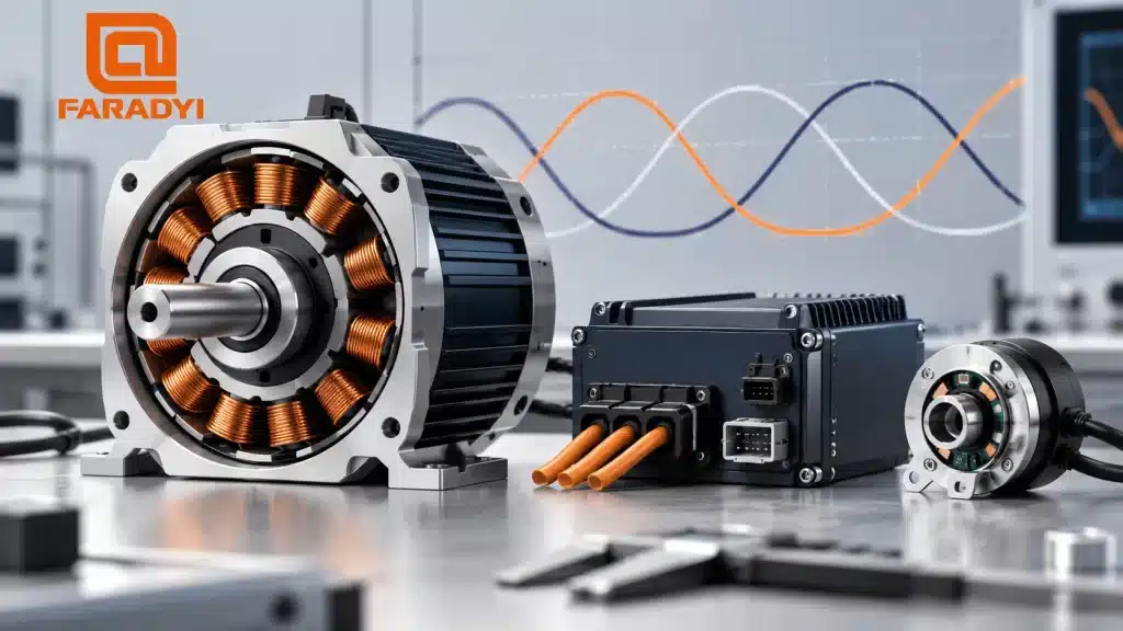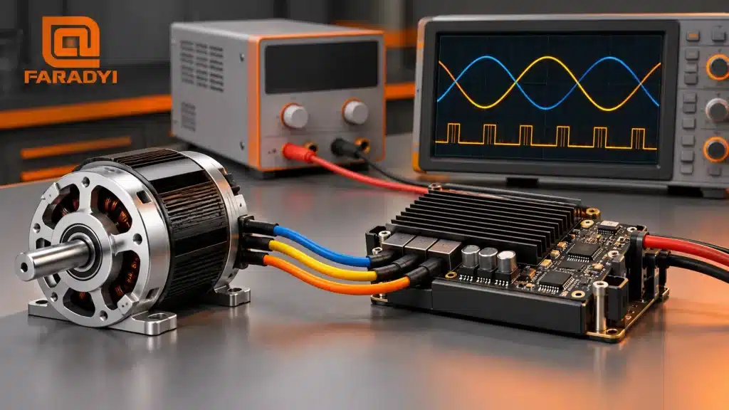
A brushless DC motor needs the controller to energize the right windings at the right time. At startup, that means establishing rotor position and producing enough torque to accelerate the load without exceeding current limits. Once the rotor is moving, speed control adjusts the drive to meet the requested rpm.
Quick answer: BLDC motor startup depends on the feedback method and the load. Hall sensors or an encoder can provide position information at standstill. Conventional back-EMF sensorless drives usually need a separate starting sequence before they can estimate position reliably. A gentle acceleration command helps, but current measurement and correctly configured protection remain important.
Why BLDC motor startup needs its own control strategy
Starting torque must overcome load torque and accelerate the rotating inertia. If the controller applies too little current, the motor may hesitate or stall. If current rises too far, the drive can trip or overheat, and the motor can be damaged.
There is no single startup time that suits every motor. A lightly loaded fan, a pump starting against pressure, and a geared conveyor have different torque and inertia requirements. Set the ramp and current limits from the motor and controller data, then verify them with the real load.
Sensored versus sensorless starting
Hall sensors and encoders
Hall sensors identify rotor sectors even when the shaft is stationary. A compatible drive can use those signals to choose the initial commutation state. An encoder can provide finer position information, although its type and the controller’s initialization procedure determine what is known at power-up.
Sensored operation is often useful for loaded starts, frequent reversing, and low-speed operation. Check sensor supply voltage, wiring, direction, and alignment during commissioning. A feedback connector by itself does not guarantee compatibility.
Conventional back-EMF sensorless control
Back-EMF falls with speed and is absent at standstill, so a controller relying on that signal cannot simply begin normal running commutation from rest. It may first align the rotor or use an initial-position detection routine, apply an open-loop acceleration sequence, and then transfer to estimated-position control.
The details differ among drivers. Some advanced sensorless methods can operate near zero speed, but that capability must be confirmed for the selected motor and control algorithm. Do not assume it applies to every sensorless drive.
| Approach | Starting information | Main commissioning concern |
|---|---|---|
| Hall-sensored | Rotor sector available at standstill | Correct Hall sequence, phase mapping, and current limits |
| Encoder feedback | Depends on encoder type and initialization | Commutation alignment, feedback setup, and loop tuning |
| Back-EMF sensorless | Normal position signal unavailable at rest | Alignment or detection, acceleration, and reliable handover |
On a phone, swipe the table horizontally.
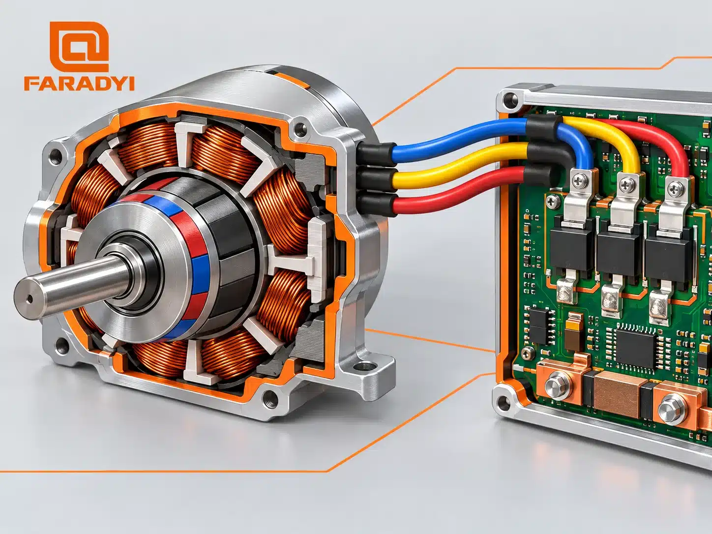
A typical sensorless startup sequence
- Check the starting condition. The drive establishes whether the rotor is stopped or already turning. A windmilling fan may need a catch-on-the-fly or controlled-stop procedure.
- Establish an initial position. Depending on the driver, this may involve alignment or position detection. Alignment can move the shaft, so account for that movement in the machine design.
- Accelerate under controlled commutation. The driver increases electrical frequency while providing sufficient torque within the motor and drive limits.
- Transfer to estimated-position operation. The controller changes over when its position signal is reliable enough. Poor handover can cause a current spike or loss of synchronization.
- Regulate speed. A speed loop, when enabled, adjusts the drive as the load changes.
This describes a common operating principle, not a universal setup sequence. Use the selected driver’s commissioning instructions for parameters and permitted limits.
How brushless DC motor speed control works
A speed command is not necessarily measured speed
A controller may accept a potentiometer, analog voltage, PWM command, or digital interface. That input requests an operating point; it does not tell you whether the motor has reached it. The controller may interpret PWM as a target speed, torque, or duty cycle, depending on its design.
Open-loop versus closed-loop control
With open-loop voltage or duty-cycle control, speed can change as load and supply voltage change. A closed-loop speed controller compares measured or estimated rpm with the target and corrects the error. Hall feedback, an encoder, or an observer may provide the speed information.
Many drives use an inner current loop and an outer speed loop. The speed loop requests torque-producing current, while the current loop responds more quickly. A speed-only design can also include hardware current protection. It is therefore inaccurate to say that speed control makes current measurement impossible.
What a soft start can—and cannot—do
A ramped command reduces abrupt acceleration demand. It is useful for limiting mechanical shock and making startup repeatable, but a PWM ramp alone does not guarantee a safe phase current. Load torque, winding resistance and inductance, supply voltage, rotor position, and the controller’s switching strategy all affect current.
Troubleshooting failed starts and unstable speed
- The shaft twitches but does not turn: check phase and feedback mapping, mechanical binding, controller faults, and the suitability of the starting method for the load.
- The power supply drops out: measure voltage during startup and review supply capacity, cable voltage drop, current limits, and protection behavior.
- Startup works unloaded but fails under load: check breakaway torque, acceleration demand, available motor current, and gear ratio. Do not raise current beyond the rated limits.
- Speed hunts after startup: review feedback quality and speed-loop tuning. Aggressive gains, backlash, or a noisy speed estimate can cause oscillation.
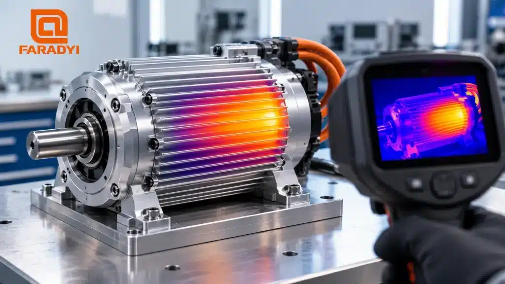
- The motor becomes hot during repeated starts: review the complete duty cycle and thermal limits, not just the steady running current.
Change one commissioning parameter at a time and record current, voltage, speed, fault codes, and temperature. Stop testing if the drive reports a fault or the motor behaves abnormally. For a motor that will not start at all, see our BLDC starting-fault guide.
Matching the control method to the application
Fans and similar loads can be good candidates for sensorless operation when the driver supports the required starting conditions. Loaded conveyors, positioning axes, and machines that reverse frequently may benefit from position feedback. Low output speed can also call for gearing rather than running a motor outside its useful range; see our brushless DC gear motor selection guide.
Frequently asked questions
Why does a sensorless BLDC motor struggle to start?
A conventional back-EMF drive has little or no usable position signal at low speed. An unsuitable startup ramp, insufficient starting torque, excessive load, or poor handover settings can cause failure.
Does increasing PWM always increase speed?
No. It depends on what the controller’s PWM input commands and whether current, voltage, load, or speed limits have been reached. Check the input specification before changing the signal.
What is a suitable BLDC startup time?
There is no universal value. Choose a ramp that accelerates the actual inertia and load within the motor, gearbox, drive, and supply limits, then verify repeatability across the expected operating conditions.
Discuss your motor and controller requirements
Reliable BLDC motor startup begins with a compatible motor, driver, and load profile. Browse Faradyi’s brushless DC motor range, then send the team your application details: supply voltage, target rpm, starting and running torque, load inertia if known, starts per hour, feedback requirements, environment, dimensions, and quantity.
Technical references: Microchip: Sensorless BLDC Control; Toshiba: Starting a Sensorless BLDC Motor.