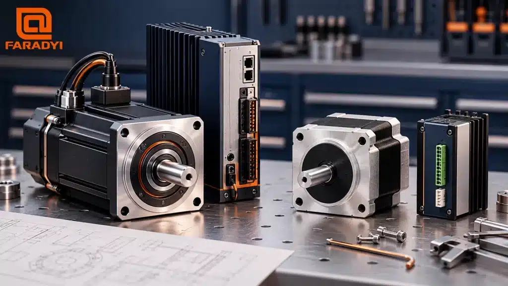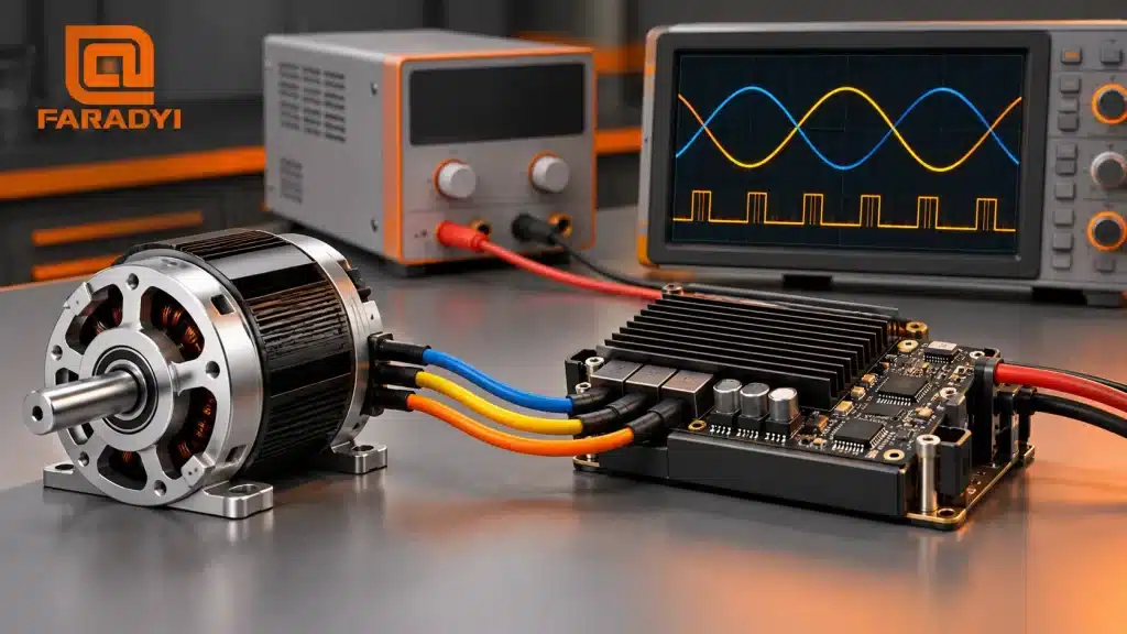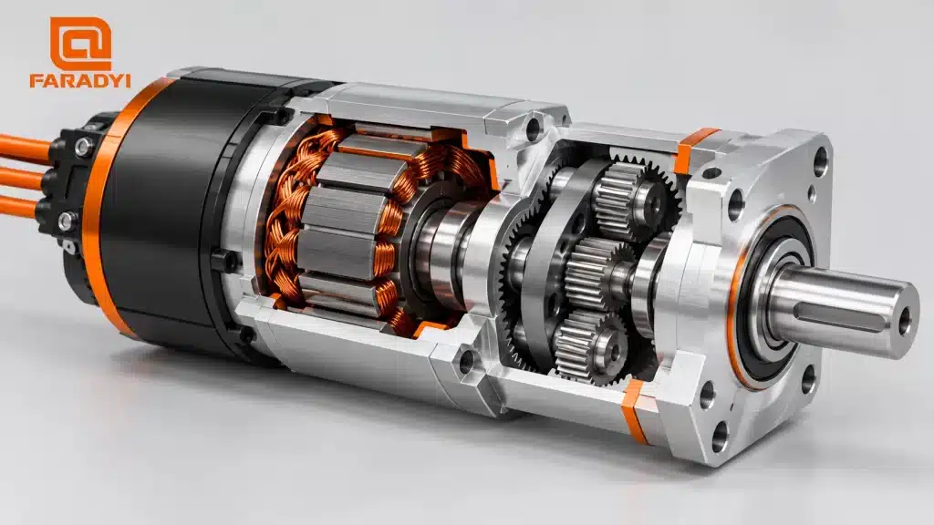
Brushless DC gear motors combine a BLDC motor with a gearbox to deliver lower shaft speed and higher output torque. Choosing one starts with the load: how fast it must move, how much torque it needs, and how often it starts and stops. The motor, gearbox, controller, and power supply then need to work as a system.
Quick answer: Select the required output speed and continuous torque first. Choose a gear ratio that keeps the motor within its operating range, check the gearbox torque and shaft-load limits, and match the driver to the motor’s voltage, current, and feedback. A gearbox has a fixed ratio, but its output speed can still change when the motor speed changes.
How brushless DC gear motors work
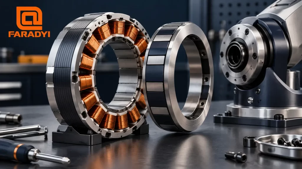
A BLDC motor uses electronic commutation to energize its stator windings in sequence. The resulting magnetic field turns a permanent-magnet rotor. The driver determines when to switch current using Hall sensors, an encoder, or a suitable sensorless control method.
The gearbox changes the relationship between motor speed and output torque. It does not create extra power: friction and other losses reduce the mechanical power available at the output. For a reduction ratio i, the basic estimates are:
- Output speed: motor speed ÷ i
- Output torque: motor torque × i × gearbox efficiency
Use the gearbox manufacturer’s efficiency and allowable-torque data for the selected ratio. An attractive calculated torque is not a reason to exceed a gearhead’s rating.
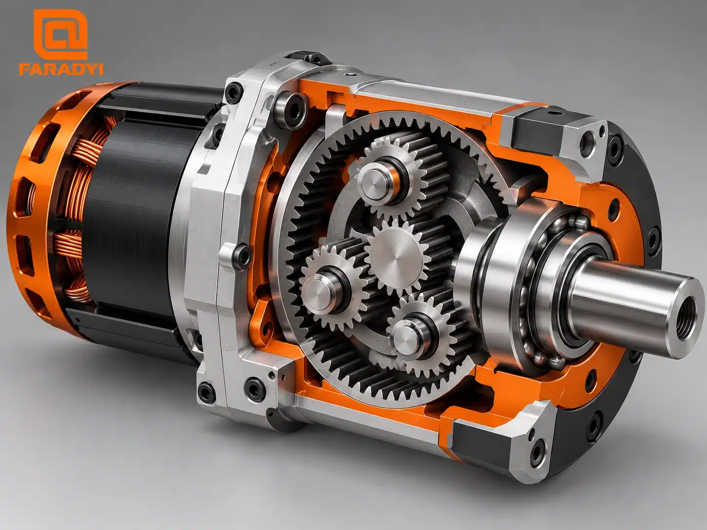
How to select a BLDC gear motor
1. Define the load at the output shaft
Record loaded speed, continuous torque, peak torque, and the motion cycle. Starting a loaded conveyor is different from running it steadily. Repeated acceleration, reversing, or a jam can place much higher demands on the system than normal running.
For cyclic applications, check RMS torque against the motor’s continuous rating under the specified cooling conditions. Check each peak separately against the motor, driver, and gearbox limits, including the permitted duration. For a belt pulley or pinion, include radial load and its distance from the output bearing; for a screw, also consider axial load.
2. Choose a ratio from the useful motor speed
Divide the intended motor running speed by the required output speed to estimate the reduction ratio. Then check an available ratio against the complete operating range. Avoid choosing a motor only from its no-load speed; use its loaded torque-speed data at the intended supply voltage.
3. Check torque, losses, and thermal performance
As an illustrative calculation, suppose a motor supplies 0.20 N·m at 3,000 rpm. A 20:1 gearbox would give about 150 rpm. If its efficiency at that operating point were 85%, estimated output torque would be 3.4 N·m. These are assumed values, not a Faradyi product specification. The actual combination still needs a sufficient gearbox rating and thermal margin.
4. Match the mechanical and electrical interfaces
Confirm mounting dimensions, shaft diameter and key, backlash, noise requirements, ambient temperature, and environmental protection. Then check driver input voltage, continuous and peak phase current, feedback type, speed command, and any required communications. A power supply must handle the operating cycle; braking can also require a strategy for regenerated energy.
| Selection item | What to check | Why it matters |
|---|---|---|
| Output speed | Loaded minimum and maximum rpm | Sets the useful reduction ratio and control range |
| Torque and duty | Continuous, peak, RMS, and peak duration | Prevents sizing from a brief maximum rating |
| Gearbox | Permissible torque, efficiency, backlash, shaft loads | Checks the mechanical limits after reduction |
| Controller | Voltage, phase current, commutation, feedback | Determines whether the motor can start and run correctly |
| Environment | Temperature, cooling, ingress protection | Establishes whether published ratings apply |
On a phone, swipe the table horizontally.
Connecting the motor to its controller
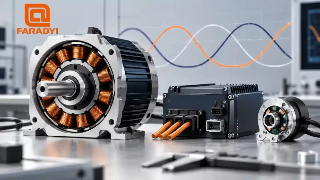
Many sensored BLDC motors have three power-phase leads plus Hall-sensor supply, ground, and signal connections. That arrangement is common, but it is not universal. Some motors use encoders, temperature sensors, integrated electronics, or sensorless operation. Wire colors and connector pinouts are not standardized across all suppliers.
- Disconnect power. Obtain the exact motor and controller pinouts before making connections.
- Confirm compatibility. Check voltage, phase-current limits, sensor supply voltage, feedback interface, and the Hall arrangement supported by the driver.
- Connect by function. Match the phase terminals and feedback pins according to the approved wiring diagram. Keep signal wiring away from noisy power cables where practical.
- Commission with limits. Secure the motor, use the manufacturer’s commissioning procedure and current limits, and begin with an unloaded or safely controlled load.
- Verify direction and behavior. Check smooth rotation, current, feedback, temperature, and fault status before applying the working load.
If rotation is reversed, use the controller’s documented direction setting or approved rewiring procedure. Randomly swapping phase and Hall leads can produce rough running, excessive current, or failed starts. Hall signals described as 60° or 120° also require appropriate driver configuration; do not assume that two connectors with the same number of pins are compatible.
Where gearing helps—and where it adds tradeoffs
Geared BLDC systems are useful for conveyors, compact wheel drives, feeders, and other machines needing controlled motion at lower speed. Reduction lets the motor run faster than the output shaft and can improve the match between a motor and a large load inertia.
The tradeoffs are added losses, backlash, noise, size, and gearbox maintenance requirements. A higher ratio is not automatically better. Precision reversing may need a low-backlash gearbox and suitable feedback; some high-speed applications need no gearbox at all.
Frequently asked questions
Can a brushless DC gear motor run at variable speed?
Yes. A compatible controller can adjust the motor speed, and output speed follows the gearbox ratio. The usable range depends on the motor, driver, feedback, load, and cooling.
Does a higher gear ratio always deliver more usable torque?
No. Reduction increases the theoretical torque multiplication, but usable output remains limited by gear strength, efficiency, thermal conditions, and the available motor torque.
Can I connect a bare BLDC motor directly to a DC supply?
A bare three-phase BLDC motor needs an electronic controller. A motor with a built-in driver may accept DC input, but its wiring and voltage must follow its own documentation.
Choosing a Faradyi motor and gearbox combination
Start with Faradyi’s gear motor range 그리고 brushless DC motors. For the control side, see our guide to BLDC startup and speed control.
To discuss brushless DC gear motors for your machine, send Faradyi your application requirements: supply voltage, loaded output rpm, continuous and peak torque, duty cycle, mounting and shaft dimensions, environment, feedback needs, and expected quantity. Those details make it possible to evaluate a combination against the actual load.
Technical reference: ElectroCraft: Selecting a Brushless DC Motor or Gearmotor.