What Is a Brushless DC Motor?
A brushless DC motor, commonly called a BLDC motor, is a permanent-magnet synchronous motor whose phase currents are switched electronically instead of by carbon brushes and a mechanical commutator. The rotor carries permanent magnets, the stator contains windings, and an electronic controller creates a rotating magnetic field that pulls the rotor around.
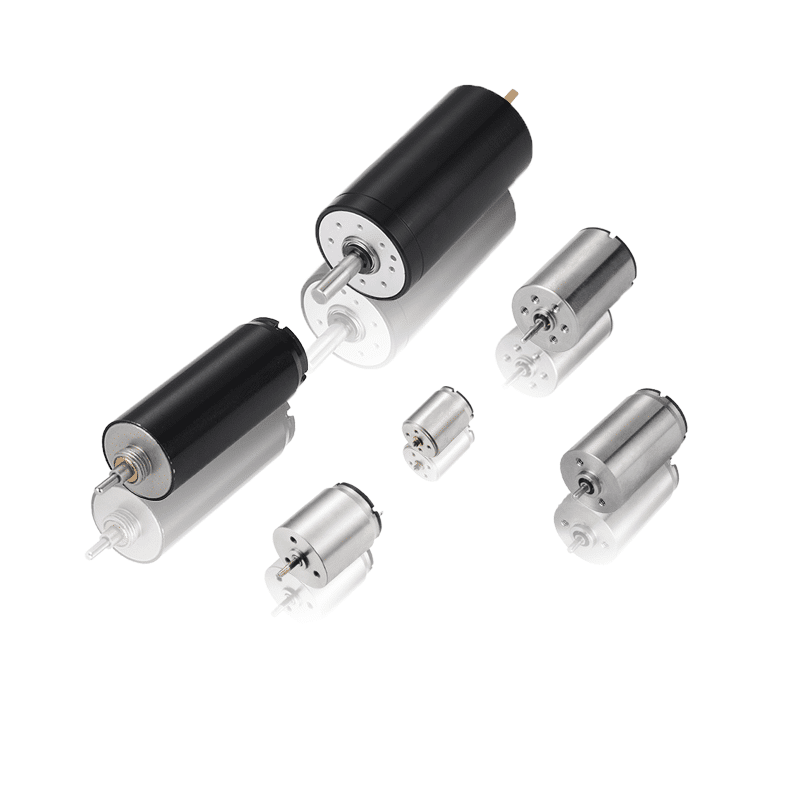
Brushless DC motors are used in industrial automation, robotics, pumps, fans, medical equipment, power tools, appliances, drones, and vehicle subsystems. They range from miniature motors for compact mechanisms to larger drive systems. This guide explains the mechanism, benefits, limitations, control options, and information engineers should evaluate before choosing one.
How Does a Brushless DC Motor Work?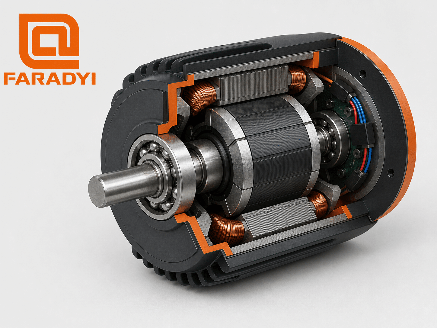
A BLDC system normally includes a DC source, electronic controller or inverter, motor, and—when the application requires it—rotor-position feedback. The inverter uses semiconductor switches to direct current through the stator phases in sequence. Each switching state changes the stator magnetic field, and the permanent-magnet rotor follows that field to produce continuous torque.
The controller must commutate at the correct rotor position. It can use Hall-effect sensors, an encoder or resolver, or a sensorless estimate derived from motor voltage and current. Pulse-width modulation (PWM) commonly regulates the effective phase voltage or current. Higher-level controls can regulate speed, torque, or position, depending on the feedback and drive.
The BLDC operating sequence
- A DC supply powers the controller.
- The controller identifies or estimates rotor position.
- Its inverter energizes selected stator phases.
- The resulting magnetic field attracts and repels the rotor magnets.
- The controller advances the phase sequence as the rotor turns.
- A command and feedback loop regulate the required speed, torque, or position.
Main Parts of a BLDC Motor System
Stator and windings
The stationary stator uses laminated electrical steel and copper windings. Lamination helps limit eddy-current losses, while winding layout influences voltage, current, torque, speed, resistance, inductance, and thermal behavior.
Permanent-magnet rotor
The rotor carries permanent magnets and turns with the shaft. Magnet material, pole count, air gap, rotor construction, and inertia influence torque density, maximum speed, response, cogging, and cost. Inner-rotor designs are common for higher-speed motion; outer-rotor designs can be useful where compact low-speed torque is valuable.
Bearings, shaft, and housing
Bearings support the rotor, while the shaft transfers torque to the load. Shaft diameter, flat or key, radial and axial loads, balancing, mounting geometry, sealing, lubrication, and housing heat transfer all affect integration and service life.
Electronic controller
The controller is essential. It performs commutation and may also regulate current, protect the power stage, accept commands, process sensors, control acceleration, and report faults. A BLDC motor should not be treated as a two-wire brushed motor that can always be connected directly to a DC source.
Sensored vs. Sensorless BLDC Control
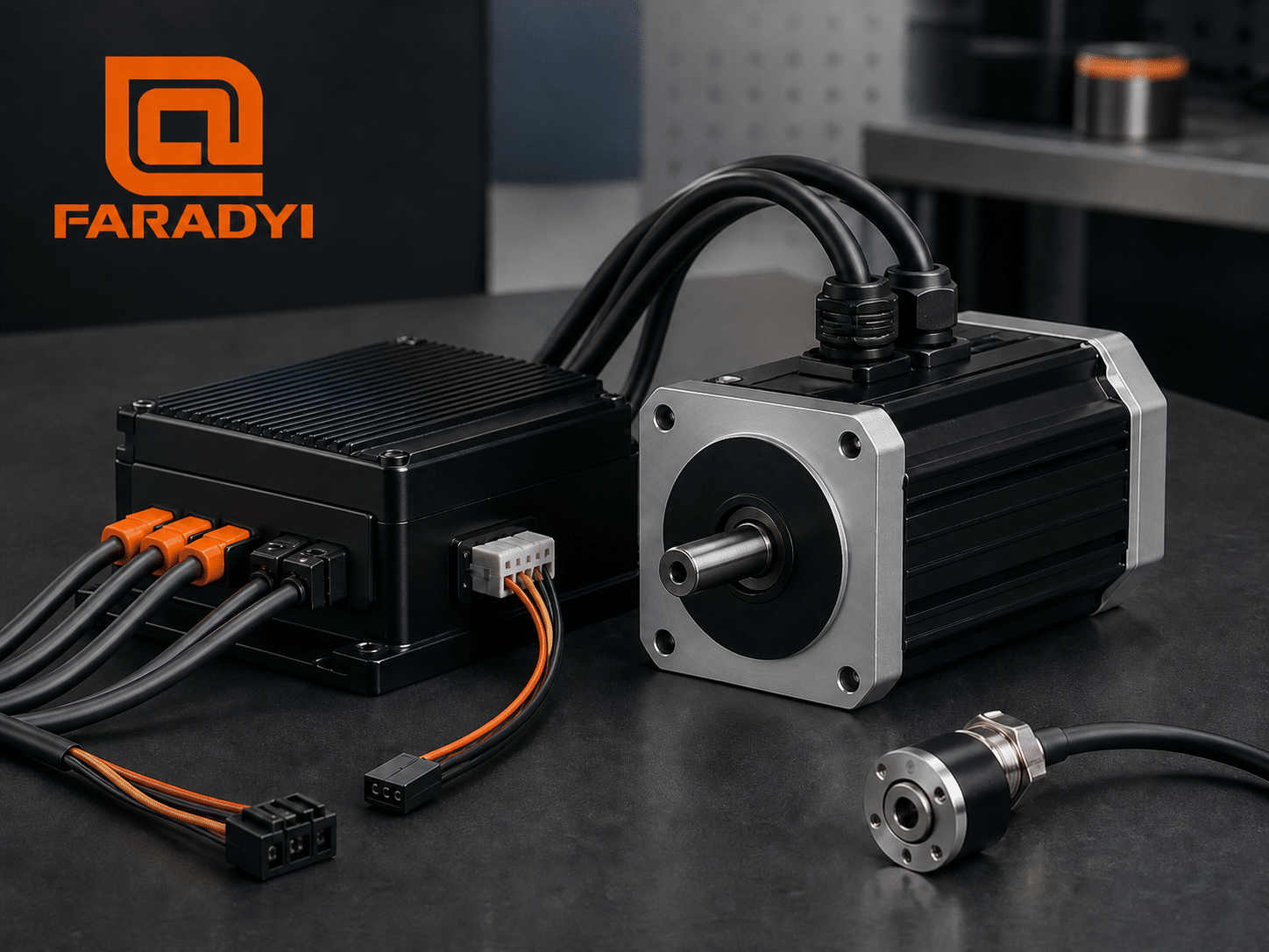
Sensored control uses Hall sensors, an encoder, or a resolver to report rotor position. Hall commutation is relatively straightforward and supports reliable startup. Higher-resolution feedback may be selected for tighter speed or position control.
Sensorless control estimates rotor position from electrical measurements. A common method detects back electromotive force (back-EMF). Because back-EMF is proportional to speed and is zero at standstill, basic back-EMF control needs a startup strategy and can be less effective at very low speed. More advanced observers and injection methods can extend operation but increase control complexity.
| Factor | Sensored BLDC | Sensorless BLDC |
|---|---|---|
| Rotor information | Physical sensor signals | Estimated from electrical behavior |
| Startup and low speed | Typically more predictable | Depends strongly on the estimation method |
| Wiring | Additional sensor wires and connectors | Fewer motor sensor connections |
| System design | Adds sensor hardware and alignment requirements | Adds estimation, filtering, and tuning demands |
| Typical fit | Loaded starts, low-speed operation, controlled motion | Fans, pumps, and applications with suitable running speed |
Phone users: swipe horizontally to view all table columns.
BLDC Commutation Methods
Six-step or trapezoidal commutation
Six-step control switches the three motor phases through six electrical states. It is widely used because it can be cost-effective and straightforward. Torque ripple and acoustic noise may be more noticeable than with well-implemented sinusoidal control.
Sinusoidal commutation and field-oriented control
Sinusoidal control shapes phase current more smoothly. Field-oriented control (FOC) regulates current components in a rotating reference frame and can provide smooth torque, efficient operation, and precise dynamic control when the motor model, sensing, controller, and tuning support it. FOC is not automatically better for every cost, speed, or complexity target.
Advantages of Brushless DC Motors
- No brush replacement: electronic commutation eliminates brush and commutator wear.
- Good efficiency potential: permanent-magnet excitation and controlled phase current can reduce avoidable losses when properly designed.
- High power density: useful output can be packaged in a compact motor, subject to thermal limits.
- Responsive control: compatible drives can regulate speed, torque, acceleration, and position.
- Wide useful speed range: the attainable range depends on winding, voltage, current, control, bearings, rotor strength, and load.
- Lower mechanical commutation noise: there are no brushes sliding on a commutator, although bearings, PWM, magnetic forces, and the driven machine can still create noise.
Limitations and Design Tradeoffs
- Controller required: electronic commutation adds a power stage, control logic, protection, and integration work.
- Higher initial system complexity: motor, drive, firmware, feedback, and electromagnetic compatibility must work together.
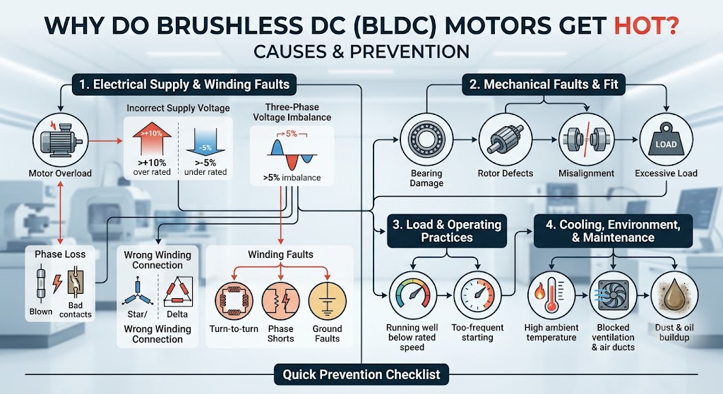
- Thermal limits still apply: winding, iron, magnet, inverter, bearing, and mechanical losses create heat.
- Permanent-magnet constraints: excessive temperature or demagnetizing current can damage magnets.
- Torque ripple and cogging: geometry and commutation can affect smoothness, especially at low speed.
- Sensorless limitations: basic back-EMF methods are weak at standstill and low speed.
BLDC Motor vs. Brushed DC Motor
| Factor | Brushless DC motor | Brushed DC motor |
|---|---|---|
| Commutation | Electronic controller | Brushes and mechanical commutator |
| Routine wear | No brush wear; bearings remain wear items | Brushes and commutator wear |
| Drive complexity | Requires compatible commutation electronics | Basic speed control can be simpler |
| Control capability | Strong potential for integrated speed, torque, and position control | Can be controlled, but feedback and electronics may be added separately |
| Best decision | Long-duty, controlled, compact, or maintenance-sensitive systems | Simple, economical applications where brush wear is acceptable |
Phone users: swipe horizontally to view all table columns.
For a deeper comparison, see DC motor brushed vs. brushless.
Common BLDC Motor Applications
BLDC motors are suited to applications that benefit from controllability, compact output, and reduced brush maintenance. Examples include:
- Industrial conveyors, pumps, fans, valves, and compact automation axes
- Robotic joints, grippers, mobile robots, and camera mechanisms
- HVAC blowers, appliance drives, and refrigeration equipment
- Power tools, garden equipment, and battery-powered machines
- Medical and laboratory pumps, centrifuges, and sample-handling devices, subject to system-level regulatory requirements
- Drones, model systems, and vehicle auxiliaries
Suitability must be established from actual torque, speed, duty cycle, environment, feedback, safety, and regulatory requirements—not from the application name alone.
How to Select a Brushless DC Motor
- Define motion: required loaded speed, continuous torque, peak torque, acceleration, direction changes, and positioning needs.
- Calculate the load: inertia, friction, gravity, transmission efficiency, radial and axial forces, and worst-case variation.
- Set electrical limits: available DC bus voltage, continuous and peak current, battery behavior, and controller capacity.
- Choose feedback and control: Hall sensors, encoder, resolver, or sensorless operation; six-step, sinusoidal, or FOC.
- Check performance curves: verify continuous and intermittent operating points against model-specific torque-speed and efficiency data.
- Review thermal conditions: ambient temperature, enclosure, mounting surface, airflow, duty cycle, winding temperature, and controller heat.
- Confirm mechanics: frame, shaft, mounting, balance, coupling, gearbox, bearing loads, cable exit, and space envelope.
- Evaluate environment: dust, moisture, chemicals, vibration, shock, altitude, electromagnetic compatibility, and required approvals.
- Test the complete system: validate maximum payload, hot and cold conditions, voltage tolerance, repeated cycles, noise, and fault behavior.
When reviewing Faradyi Motor’s brushless DC motor options, use the controller and load conditions intended for the final machine. A no-load speed or isolated motor rating is not enough to qualify an application.
Frequently Asked Questions
Does a brushless DC motor need a controller?
Yes. A BLDC motor needs electronic commutation. The controller switches phase current according to rotor position or an estimated position and may also regulate speed, torque, current, and protection functions.
Is every BLDC motor sensorless?
No. BLDC systems may use Hall sensors, encoders, resolvers, or sensorless estimation. The best method depends on startup load, low-speed behavior, accuracy, cost, wiring, environment, and controller capability.
Can a BLDC motor run from a battery?
Yes, when the battery voltage, current capability, protection, wiring, controller, regeneration behavior, and motor ratings are compatible. Battery voltage changes with state of charge and load, so evaluate the full operating range.
What controls BLDC motor speed?
The controller sets the electrical commutation rate and regulates voltage or phase current, commonly using PWM. A speed loop can use Hall transitions, an encoder, or a sensorless estimate to compare actual speed with the command.
Are BLDC motors the same as PMSM motors?
Both are permanent-magnet synchronous machines, and terminology overlaps. “BLDC” often refers to trapezoidal back-EMF and six-step commutation, while “PMSM” often refers to sinusoidal back-EMF and sinusoidal or field-oriented control. Actual motor waveform and controller requirements should determine compatibility.
How long does a brushless DC motor last?
There is no universal service-life figure. Bearings, temperature, speed, load, balance, contamination, lubrication, vibration, electronics, and operating cycles all matter. Use model-specific life data and application testing when life is a critical requirement.
Discuss Your BLDC Motor Application
Understanding what a brushless DC motor is is the first step; reliable selection requires matching the motor, controller, feedback, supply, mechanics, and environment. The best design is the one that meets loaded performance and thermal requirements with appropriate margin.
Explore Faradyi Motor brushless motor solutions and send the engineering team your supply voltage, loaded speed, continuous and peak torque, duty cycle, dimensions, shaft and mounting needs, environment, feedback method, controller or communication requirements, and expected quantity.
Technical References